Trying to get LED drivers that run higher voltages/currents is a pain. Standard options are currently:
- Pay as much as the LED probably cost for a decent driver.
- Get an eBay driver, hope it doesn’t blow within the first week, and hope that the true rating is at least in the same ballpark that’s been advertised.
- Use a computer PSU (high power, lowish cost) and use some converters to bump up the voltage.
For my latest LED assembly, I opted for “none of the above”.
Warning: This is pretty dangerous and you could get yourself (or someone else) killed. There’s a reason this isn’t a common way of providing power. Oh, I also could have said something totally wrong that would lead to your demise if you tried to replicate it. In other words, this writeup could be riddled with errors. CONTINUE READING AT YOUR OWN RISK!
The premise I worked from which is essentially a “simple” version of the device I put together looks like this:
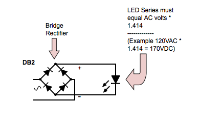
Basically, you:
- Find out the AC voltage from the wall (often ~120V in North America). This is your RMS voltage.
- Multiply it by 1.414 to get the “peak” voltage (what AC voltage truly hits at it’s max). If the wall voltage was 120V, this would be (120 x 1.414) = 169.7 volts.
- Run LEDs in series to meet that voltage value (169.7 volts in this example, though a bridge rectifier will probably shave off 1 to 1.4 volts for you already).
- Connect the AC mains to a bridge rectifier, and use the DC output to run those LEDs.
On it’s own, it’s simple. Unfortunately, it can be pretty dangerous (for just one of the reasons, search YouTube for “DC knife switch” to see some of the fun that high voltage DC is capable of).
Matching up the LED voltages is critical. If you can’t quite reach your peak voltage (169.7 in the example), you’ll probably have to use resistors to make up the difference, which will drop your efficiency from 99.9%+ to something quite horribly low. Oh, and since household voltage can fluctuate and your LEDs are at risk of thermal runaway with this semi-constant-voltage, you probably don’t want to aim for the max current the LEDs can support.
Another negative: since your 169.7v worth of LEDs probably turned off below voltages in around the 100-140v range (they tend to have minimum activation voltages), your leds will flicker like crazy – after all, the rectified voltage will be constantly bouncing between 0-169v at the same rate at AC (60hz*2 = 120hz in North America). Technically they might be on less than 20% of the time. Perhaps even less than 10%.
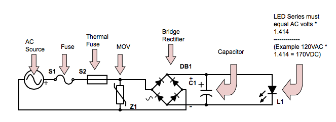
Adding a capacitor can help out with that last one.
While you’re at it, some fuses and a MOV might be beneficial. Here’s what I came up with for my final device:
Capacitors
I went fairly low for the capacitors. My series LEDs pulled around 350mA at the peak voltage, and I used 2x 33uF capacitors for a total of 66uF. Between some math, looking at data sheets, and doing some rough guessing, I figured that the LED’s should pulling somewhere in the rough ballpark of 20-50mA at their minimum with those caps, although since the voltage-current curve of LEDs isn’t straightforward, that really is closer to a guess.
In usage, the output of the LED’s can sometimes be noticed flickering at certain light distances, but since this unit was for giving spruce seedlings some grow lighting, I was perfectly fine with it. If I had wanted to keep the voltage/current from dropping much at all, I likely would have needed between 500-1000uF which would have been problematic when it came to physical size.
Worth noting that capacitors were cheap enough that I grabbed ones rated for 10k+ hours at higher temps, high voltages, and with some solid ripple tolerance.
LED’s
I went with 4x Vero 10, and 2x Vero 13, because in series they made up that 350mA current at the peak voltage. Why aim for such a low current? The big reason was because I wanted a lot of headroom in case there were power surges, cooling issues, etc. I could have worked other combinations to get 700mA (or higher) which these Veros can handle, but the problem was that if the line voltage moved to 125V or more, the current would move up to about an amp. That would create more heat, which would lower the forward voltage, and eventually I’d be hit with thermal runaway. A nice soft setting of 350mA really minimized those risks. Other reasons for choosing 350mA had to do with efficiency, and the basic fact that this was my first custom system run direct from a bridge diode.
As it turned out, during the first few hours of usage our voltage at the wall jumped back and forth by about 6V. What this meant was that sometimes the LEDs pulled a total of 6W, and other times pulled over 20W. Yes, LEDs are very sensitive to small voltage changes.
The MOV
You’ll notice a MOV in there for surge protection. It basically does nothing unless voltage gets too high, in which case it connects the live to the neutral (basically a short circuit) to protect the LEDs (and ideally blow a fuse if the surge continues for any length of time). Again, I didn’t go with the cheapest one here.
Fuses
You’ll notice 2 fuses in that diagram. The first is a standard “fast blow” fuse. I could have easily got away with a 1A fuse but chose a 2A just because it was a permanent soldered fuse and I didn’t want it blowing if a half second power surge caused a 1.5 amp draw.
The second fuse is a 1A thermal fuse. This has a triple purpose:
- If temperatures get too high, I start running the risk of the LEDs going into thermal runaway. Since all the aluminum is connected together, this should blow before the LED’s get damaged due to temperatures.
- At the low current I’m running, the components inside shouldn’t get too hot. The bridge rectifier should maybe put out 1/3 of a watt (and it’s heatsinked). The capacitors shouldn’t get terribly warm either. So if temperatures in the circuit actually get high, something is probably wrong. Hence, the fuse.
- The MOV. If it actually eats some surges, it might start to fail. When MOVs fail, they have a tendency to permanently short-circuit even at “intended” voltages, which means they can heat up to the point where they’ll start on fire. The thermal fuse is actually up against the MOV – if the MOV does decide to pack it, it should blow the thermal pretty fast, long before it would catch on fire and wreck the other components.
Dollar-wise, I went fairly cheap with the fuses.
The Bridge Rectifier
This was a pretty standard rectifier rated at 3A / 1000V. They’re again cheap enough that I figured it’s worth getting one which is over-rated. I was sure to get one with a through-hole though so I could easily mount it to a heatsink.
The Final Product
Here’s the complete LED assembly, in action and all put together (click for larger images):

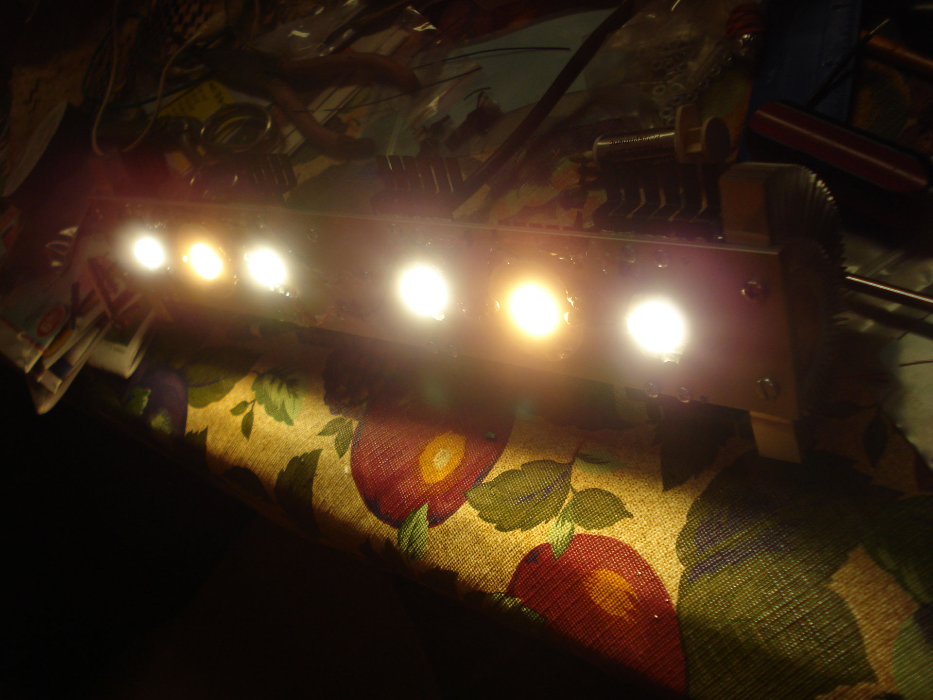
It’s definitely the nicest-looking assembly I’ve made so far. It also required the most holes drilled (a grand total of 36!) and a lot of thermal paste.
It’s virtually all aluminum (aside from copper inserts in the side heat sinks).
The aluminum box containing all the components can be seen in the center. At only 2×2 inches (and just over an inch high), it was a really tight squeeze to get all those components in there and it took a few hours to make sure everything was routed in a way that would fit while I carefully soldered and secured everything. If I were to do it again, I would definitely go larger.
The 10 black heatsinks are standard 10W component heatsinks. I used them because they were considerably cheaper than the more “typical” heatsinks while being light in weight, and gave a lot of extra surface area for passive cooling.
A closer look at a side heatsink:
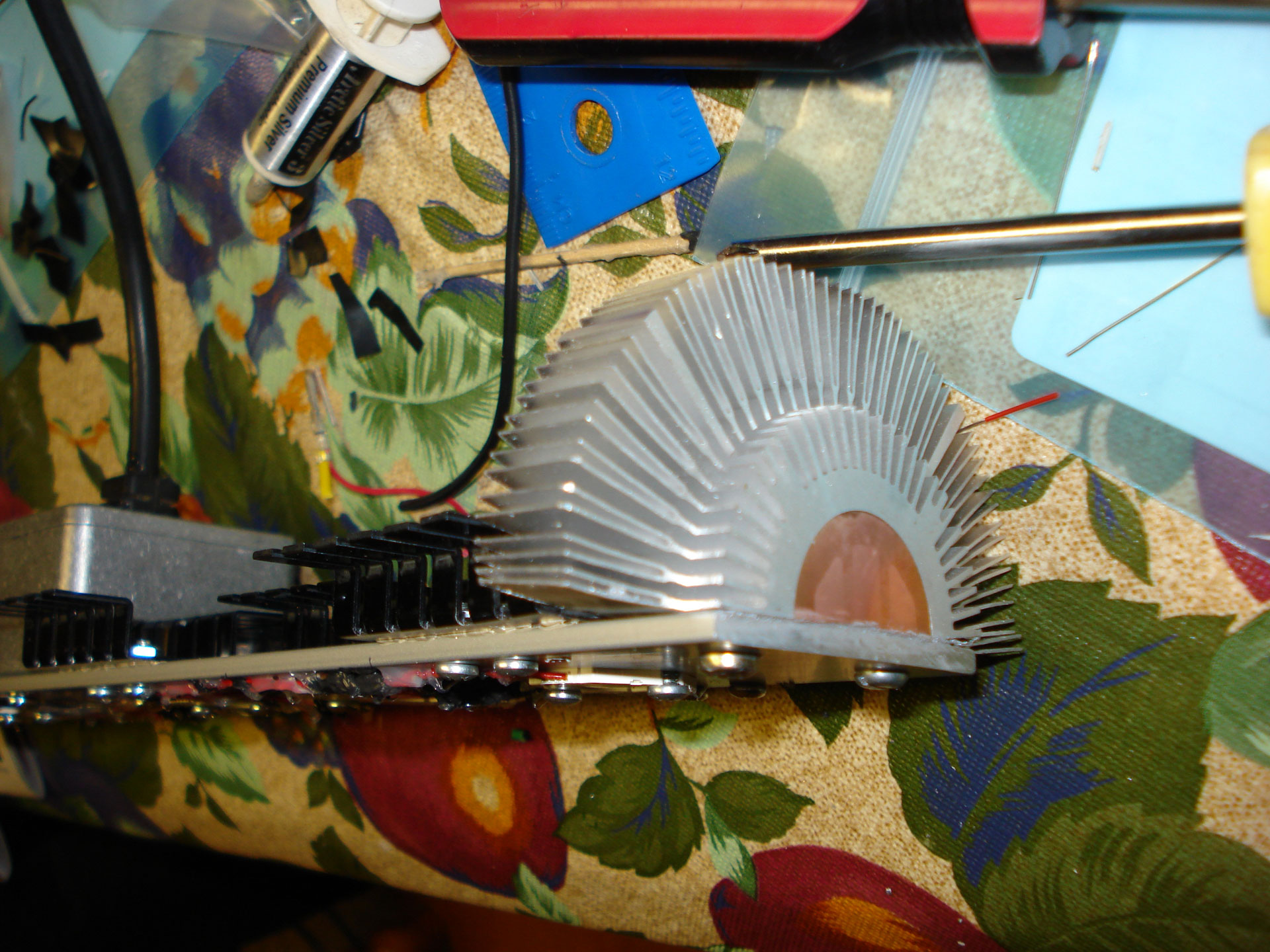
I cut an Intel CPU heatsink in half and mounted the halves. This was the hardest thing to cut and drill – both the aluminum and copper were pretty solid.
—
Final Thoughts
I’m quite happy with the setup. The hottest portions of the unit (near the LED’s themselves) have capped at just below 30˚C with most of the outer areas between 22-24˚C. When our household voltage hits it’s daytime peak, I’m looking at below 40˚C.
I’m looking at over 99% efficiency in terms of the power “supply”.
Biggest downside I’ve come across so far is the variable voltage (and thus, current). Remember, I’ve seen from 6W-20W so far depending on where the mains voltage has fluctuated to. That’s a pretty substantial range when you think about it. Carefully sizing the LEDs and throwing in as many extra precautions as possible is something I’m glad I took the time to do.
That varying voltage means it’s probably not a system that would work well for LEDs that were being driven hard and don’t have that extra headroom.
In any case, time will tell, but so far I’m calling this one a success.
Even a 10 ohm or smaller helps the balance.
If you want to get fancy, add an LM317 to the circuit at whatever A or MA you need. This works great