If you’re using the MSI X58 PRO-E motherboard and have checked out the temperatures in your BIOS, you might be alarmed to find that the IOH temperature (northbridge) is quite high. Indeed, a little searching around will show that you’re not alone – plenty of these motherboard owners have expressed similar concerns.
The good news is that Intel designed the X58 northbridge to safely handle temperatures of up to 100 degrees celsius, so if you’re not quite there, technically, you should be safe.
The bad news is that if you’re flirting with high 80’s or 90’s already, a bit of overclocking or a hot day may very well put you over the top.
If you’re concerned about temperatures, you have a few options:
- Contact MSI and inquire about an RMA. Note that unless your temps are actually passing 100 degrees, they may simply tell you that it’s operating within design limits… which is true.
- Keep the environment cool, be careful with overclocking, and hope for the best. Worst case scenario is the motherboard dies outside of the warranty period. Chances are you’ll be fine.
- Add some internal cooling. Internal fans help, or you can glue a little fan to the heatsink.
- Upgrade to an aftermarket cooler. Pricey, and it would probably cost less to simply buy a motherboard with better default cooling instead, but it’s an option.
- Remove the thermal interface pad from the Northbridge/Southbridge and apply some high-quality thermal paste instead.
Option #5 is the one we’ll be looking at here.
Step 1: Remove the heatsink mounting screws from the back of the motherboard.
There are 2 screws for each the northbridge and the southbridge. Both have springs and a black rubber washer – don’t lose them, and don’t forget to install them later! Note that there are also 2 screws for the mosfet cooler – DO NOT REMOVE THEM, as you won’t be removing the mosfet heatsink. Not only to the mosfet’s already run fairly cool, but if you remove the heatsink & peel off the pad you’ll have contact issues when re-installing (I removed it in the video and gave the reasons/workaround there – suffice it to say with the work involved for something very much un-needed I probably wouldn’t do it again).
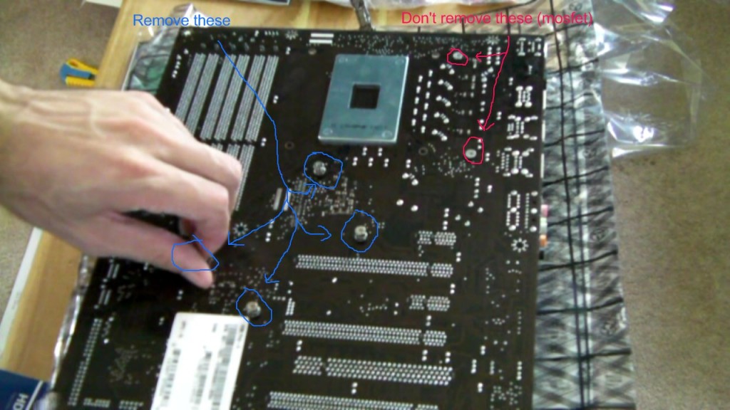
removing the 4 heatsink screws
Step 2: Take off the northbridge and southbridge heatsinks.
With the screws removed, you can now work at wiggling the heatsinks until they come off. Note a few things here:
- Because the northbridge and southbridge heatsinks are connected via a heatpipe, both have to come free at the same time – otherwise you may bend/crack the heatpipe.
- The easiest way to get them free is to wiggle them both at the same time. Wiggle in different directions – clockwise, counterclockwise, up, down, etc.
- It will take time. Be patient. Don’t force anything, and don’t be tempted to “pry” the heatsinks up with anything (a screwdriver has a very good chance of damaging your motherboard). You also want to be gentle so that you don’t crack/break the die on the northbridge. If you crack it, the motherboard’s toast.
- It took me close to a minute. It may take you longer. If the heatsinks absolutely won’t budge after a few minutes of wiggling, you may want to leave it be – it’s not worth damaging the motherboard over.
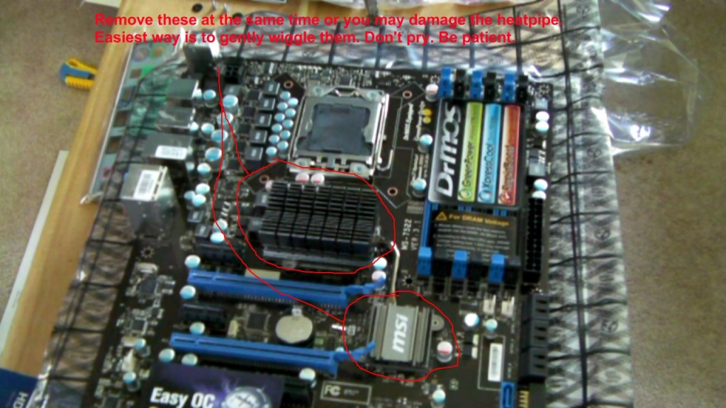
the 2 heatsinks to be carefully removed
——
Step 3: Once the heatsinks are off, clean up the remaining thermal pad that’s stuck to them.
You can use a razor to scrape the pink gummy material off the heatsinks as long as you’re careful not to gouge them. A little isopropyl (rubbing) alcohol can help too. Don’t use anything metal to clean off material that may be stuck to the northbridge itself though – just use the isopropyl and nothing harder/sharper than a fingernail to gently scrape off the old material.
One thing to note is the black fuzzy square surround on the northbridge heatsink – don’t remove it – if you do, you may short out the northbridge when you re-attach it. If you accidently scraped it off, you may be able to make a new surround out of electrical tape.
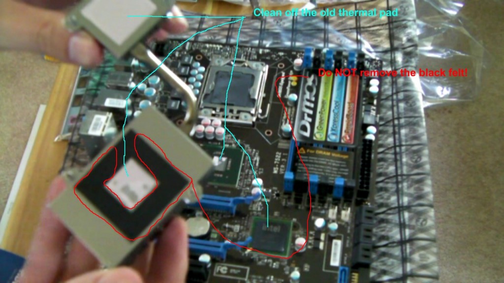
remove the old thermal pad – you can use rubbing alcohol or gently scrape with your fingernail
Step 4: Apply a small amount of (preferably non-electrically-conductive) thermal paste to the center die of the northbridge, and to the southbridge.
Non-electrically-conductive paste is very very highly recommended. We’re well past the days where metallic pastes were better, so you should be using non-electrically-conductive pastes already. There are 2 methods you can use to apply it. The first is the “drop/line” method where you put a small drop (or line) of paste across the center and simply let the heatsink spread it out. The 2nd method is the “credit card” method, where you apply some paste and use a credit card to apply it uniformly and evenly across the contact point of the chip, thin as can be. Both methods have merit, and various tests have shown that the end result is almost exactly the same.
Note that if the paste you’re using is electrically-conductive, you have to be extremely careful about applying it and ensuring that it doesn’t end up somewhere it’s not supposed to go. You have to be very clean and precise.
——
Step 5: Test the contact area before reattaching the heatsinks. Then, attach the heatsinks.
Because the paste is thinner than the old material, you want to make sure that the paste is indeed making contact with the heatsink. Simply grab the heatsink, put it in place on the motherboard by hand and use finger pressure to hold it on for a few seconds. Then take the heatsink off and take a look – if it’s still clean, you may need to apply the paste a little thicker. If it looks like it’s got good coverage, then you should be fine.
Once you’re sure you’re getting good coverage, put the heatsinks on and hold them in place while you flip the motherboard and attach the screws. Don’t forget the black washers and the springs!
——
Step 6: Optional (I recommend you skip this): Replace the thermal pad on the mosfet heatsink with thermal paste.
The mosfet’s don’t really need much at all in the way of cooling. The only reason I removed the pad on the DrMOS heatsink and switched to thermal paste is because I didn’t realize the amount of time, work, and modification it would involve. You could very easily damage something by removing the thermal pad, and thus I highly recommend you do not do this! That said, if you choose not to heed this warning and are determined to do it anyway, I’ll try to help you out here regardless.
The big issue is that the mosfets are actually slightly below other components. Normally, the heatsink would touch these components, probably shorting them out – however, the pad that MSI uses is so thick that it elevates the heatsink enough that it doesn’t touch. If you’ve taken off the heatsink and pad already, put the heatsink in place and rock it a little – you’ll notice it doesn’t sit flat on the mosfets – one edge is held up by the components on the CPU-side, and the other edge barely touches the mosfets.
To get around the contact issue, you have to grind down the edges of the heatsink. To determine where to grind, you’ll have to put a thick layer of paste on the mosfets, place the heatsink, take it back off, and look to see where the 5 squares are. You then have to mark where you’re grinding, and pull out the bench-grinder or dremel to remove as much material as you can from the edges you marked. If you grind too little, you’ll have contact issues. If you grind too much, you’ll take off some heatsink fins. Finding the happy-medium isn’t fun.
Next, just to make absolutely sure you’re going to short anything when the heatsink is installed, you’ll have to cut a lot of pieces of electrical tape and use a tweezers to get them in place completely covering all the tiny components around the mosfets. You could probably use a tiny brush along with form of non-conductive paint instead, but electrical tape is likely safer. Once you’ve taped off everything but the mosfet’s themselves, put the heatsink on and double/triple-check that you’ve got everything covered that it could touch.
If everything looks good to go, you can install the heatsink…. except that you’re also going to want to cut a tiny spring to use with the screw (to make it similar to the screws/springs for the north/southbridge). The heatsink didn’t need the springs before because the pad was so thick – now that you’re not using a pad, the screws are holding the heatsink in place, but not holding it tight. The springs you use have to be about the same diameter as the northbridge/southbridge springs so that they don’t slip and short something. They also shouldn’t be too long, or you’ll keep the screws from going in all the way. Finding the perfect balance is very difficult – both springs I used were cut to between 1-2 coils in length. Since your springs will undoubtedly be different, you’ll have to find your own “best fit”.
Finally, you want to make sure the thermal paste is contacting the heatsink. Depending on how much the components between the mosfets are sticking up (and depending on how much height the tape adds), you may not be able to get the heatsink close enough for a really snug fit. You could do some further grinding to the heatsink (between the mosfet locations this time) to alleviate this, but by the time you’ve come this far you’ll probably be content to just layer on the paste a little thicker.
Again, it’s not worth the work/hassle/risk, but that’s how you do it if you’re so inclined.
——
You should be done! Reinstall the motherboard and hopefully your temps should now be lower than they were before!
3-way SLI Y
Hybrid SLI N/A
CrossFire Y
Hybrid CrossFire N/A
this mother run two gtx 295 ??
There are 3 slots, and you'd be populating 2 of them. If you use the 1st and 2nd slots, you should get x16/x16. If you added a 3rd card I believe you'd get x16/x8/x8.
Obviously, make sure the power supply you buy is powerful enough to run both cards.
A friend of mine bought this board and would like to repaste the chips (not the mosfets, I hope). I have some left-over Artic Silver paste that I used effectively on a CPU installation. We were assuming we'd use this paste for this X58 job, but your advice to avoid electrically conductive paste has me reconsidering this. The Arctic Silver claims to be mostly silver, so it's presumably very conductive. Do you advise against the AS paste for this application? If so, would you recommend the Arctic ceramic paste (I forget the trade name) or what? Thanks for your help!
For the northbridge/southbridge, Arctic Silver should be alright. The big problem in my case was that the northbridge heatsink was flush, but the heatpipe elevated the southbridge a little, so I needed to put the paste on thicker there to get good contact (the spring loaded screws don't have enough pressure to counter-act the heatpipe pulling up). If the paste goes on too thick and runs down the chip, it may short something.
So you can use it, just be careful that you use enough paste that there's good contact, but not so much that it runs down and fries the motherboard. Since you'll have to pull the heatsinks on & off to check, there's the added fun of making sure it doesn't smear/slide and get all over the place. Non-conductive pastes are nice because you can be a bit sloppy, you can make mistakes, and nothing tends to short out.
As far as the MOSFETS, Arctic Silver would just be asking for trouble. It has to go on thick to make contact. It will run down. It will almost certainly short something. Just doing the MOSFET's is a risky enough procedure. Using AS on them would be like russian roulette but putting 5 bullets in the gun instead of 1. All for no real gains. Strongly discourage your friend from doing them at all - it's really not worth it.
Finally, for pastes, Arctic Silver Ceramique is probably the non-conductive one you're thinking of. There are quite a few non-conductive pastes out there - Arctic Cooling MX-2, Noctua NT-H1 to name a couple. Really, all of them are fine.
Best of luck!
Thanks very much! I was already sensitive to the possibility of small issues resulting from the difference in thickness between the stock goo pads and the elegant, thin layer of AS5. But I hadn't considered unequal contact due to the pressure of the heatpipe. It's great to know the trouble spots before you get knee-deep in them.
Thanks so much for the informative, complete writeup on this issue.
As you might guess, I am a new owner of an MSI PRO-E motherboard (April 2010), mated with my new i7.
CPU temps are great ( 23C at idel!) , courtesy of a couple of Scythe S-Flex case
fans and a Zalman CNPS10X-Quiet chiller.
My IOH was running at about 81C at idle though!
Following your guide, the Northbridge popped loose easily, but the Souhtbridge was firmly attached. I used a wooden chopstick to gently pry up the lugs on the Southbridge, and from there it was easy. Linux sensors now reports "system" (aka Northbridge IOH) running at 67C at idle. Still a bit high for my taste, but well within design limits.
Thanks again.
-don
idle around 75-80c is very hot
Thanks Matt for a great article.
It was 70°-75°C Before and now 40°-43°C with a 60mm fan w/custom airduct
I am going to attempt this procedure this weekend, and it seems like many are getting great results with it. It's really ridiculous that MSI didnt add better stock cooling to this. All that was a needed was better quality paste, and a lil 40mm fan like many other manufacturers have. Honestly, this board should have been recalled, because it is unfair of them to expect people who buy these pro/pro-e boards to have to spend additional time and money to use them. But they obviously didnt want to do a recall and have to eat the costs on them.
I read a classic thread on their forums, with some guy who showed tons of pics and a reworking to get the temps down, and the pics of the TIM were just beyond terrible. He had an Eclipse board, which just like the Pro, use this purple gum/cement crap, and it just basically is impossible to get off and with the board running so hot, it pretty much gets welded on there. Couple this, with the poor stability of the push pins, the contact is also terrible. Did my homework on this, and the PRO-E doesnt use push pins, since MSI started listening to people a bit. There was a revision of the PRO-E that had a black colored board, rather than the initial reddish-brown ones (the one i have, lucky me uhgg lol). Unfortunatetly, many Pro-E's were still using that awful purple gunk, and they finally stopped using that in late 09/early 10, and started using a greyish paste that was a lil bit better, but still not all that great, but way easier to remove the heatsinks from. What they need to stop doing is lining the NB/SB heatsinks together, because as you stated, it may not allow for them to both be flush. It's just a silly set up and they should really be separate and would allow for easier aftermarket modding to be done.
Now, i was going to go with the thermalright hr-05 SLI heatsink, you have heard of it. Many in that thread used it and got good results, but many also just did what you outlined and got virtually the same temp decreases. So i figured, why spend money on that if it aint needed. And as you pointed out in your youtub vid, the SB has to be replaced (though if i did go that route, i would just hacksaw it off, and use the SB heatsink still, since it never gets hot anyway. SB is always lukewarm/cool even on full load, so doesnt need much cooling).
I just bought this system with an i7 2nd gen chip in it @3.2Ghz (water cooled with an H50 from Corsair), 6gigs of ram, gtx460 in it, 200mm side fan, 120 in the front and back, which ill be replacing with 2 more 200mms, Win7, and it all runs really nice. This heat issue though is the only damn problem, but its a big one. Im running 78-80 daily and this is just going to reduce the mobos life more n more like this :( Everything else runs great temp-wise, nothing over 40, hell, CPU is at 19, and the cores under 35.
The questions i have for you though, have to do with the padding you removed in your video. Now yes, the black one i know has to ALWAYS stay on as to prevent any shorting. But i noticed the SB doesnt have that. All it had was the original goop, and what looked to be a pad of some type. I just want to be sure if that can all be scraped/cleaned off.
As another user also pointed out, the AS5 is conductive, and me being a first timer for this kind of mobo work, i really DO NOT want to be using that. People rave about it and say its the best out there, but all i need to do is have some of it drip off the sides or whatever, and then im totally out of a system for awhile and that is something NO ONE needs to be dealing with. Just how much paste am i supposed to use here? I watched some vids of a guy doing one with a CPU HS, and well...man, he barely used any. He mentioned the grain of rice, and also the pea size amount, but it just seemed like way too little. I noticed in your vid you had what looked to be all of it evenly covered up. Is it a good idea to also put the same amount on the heatsinks as well, and then contact them together have it's own weight evenly distribute the rest? If i was to put on bigger goops of it, and then put the sinks on, im afraid it would leak out the sides lol. Whether its conductive or not, i really dont want that stuff getting on any of the copper lanes of the mobo, or on a capacitor, as those things need to be left alone and not have unwanted material on them. I get enough dust and damn cat hair as it is lmao.
So yea, just wanting some more clarification on all of this. I know this original post is old, so not sure if youll even notice it, but hopefully ya will :D
You're right - southbridge doesn't have that black "pad" - just the thermal gunk that can all be scraped off.
As to the amount, I used what's known as the "credit card" method to scrape the paste thin (basically put down a drop and spread it with a credit card or another flat plastic item to get it as thin as possible and remove the excess). The "drop" method would probably work too, though it's tough to gauge how much you'd need, you'd probably have extra spilling off the sides, and it might end up being thicker than you need. Whatever method you use, you're probably best not to use a conductive paste either way, because if somehow you get some squeezing out onto the electronics, that stuff is a mess to try and remove. Noctua makes a non-conductive thermal paste, although if you want to go with the Arctic brand, they make a non-conductive paste known as "Artic Ceramique". Actually there are plenty of non-conductive pastes, so there should be plenty of options there.
As a final reminder, when you place the heatsinks back on, pull them off again and make sure some paste TRANSFERRED on BOTH heatsinks. If it didn't transfer, you might have an air gap on one, in which case you need to apply a little more paste (and try again).
Best of luck.
I decided to go with Arctic MX-4, since its non conductive and right up there with some the most used.
What really has be worried so much, and the ONLY thing, is getting them damn things off. I seen several people, even on MSI's own forums, saying the SB was a real hassle to get off, and a couple never even posted back, making me believe they gave up :-/ That is why i am praying its not that old purple cement they once used. I mean, heck, i bought this back in June, and it would be quite odd to be getting a mobo that they were still using that terrible TIM with. But yea, everyone said the NB came off easily, but the south wouldnt budge and took many a long time to finally get it loose. The guy who posted all them pics, actually kept the NB heatsink, but bent it back and replaced it with his own. Lol it was just hanging over the sata ports. Eventually, he hacked it off, but it just looked so weird like that.
I just hope this darn thing comes off easily, i really need to change this out asap, i hate being at 80 degrees most times :(
Thanks for all your help though, Matt, definitely learned a lot from all your info here, and ill post back with the results soon.
http://forum-en.msi.com/index.php?topic=126885.0
The hair dryer's not a bad idea, though I'd be a bit hesitant to run warm dry air over everything (potential for static buildup). Once the pad's a little warm it should be a little more malleable though, and you should be able to twist a little more each direction - really once it budges even a slight bit back and forth, wiggling should go further each time. The other thing you could try would be a soldering iron pressed against the heatsink in very short intervals, but that starts getting fairly risky. You'll get higher heat then with a hair dryer, but if it gets too hot (which can happen *very* fast) you'll end up exposing the components to temps they're not designed for which could potentially cause damage. Not to mention, there's the potential to burn yourself when you grip the heatsink.
Keep in mind that you should be able to apply a little more force to the SB heatsink than you did with the NB - the NB has an exposed die, and they're pretty brittle. The SB is the standard large black chip and should be a fair bit more durable.
Best of luck.
Well awesome news, Matt, i am not messaging you from the comp with the Pro-E in it, and all i can say is WOW. 82 degrees, down to 49!!!! I mean, WOW. Now THAT, is one helluva difference eh? I managed to finally get that darn SB HS off, took me a good 1/2 hour on that one, but i stayed patient and calm, and just kept wiggling softly and then a bit harder as it loosened. Once it gave way, i felt like i just climbed Mt Everest lol. And yea, you're right, it looks like a normal chip like others on the board with a 'rubbery' top, rather than an exposed die like the NB. I was EXTREMELY careful with the NB as well, because when you said if the die cracked and the mobo would be 'a piece of garbage now', that made me gulp when hearing that, so i took extra care with that part of it.
As for the bad news, well my god, what was MSI thinking with that TIM they used? Supposedly, some were changed to a white paste once people complained enough, but i wasnt lucky enough to get a Pro-E that had it. One plus is the Pro-E never used push pins, but the crap they used for paste was just downright terrible. It took me 2 hours to clean it off, it was this pink looking bubble gum nonsense, very hard and dry, and i think even Maguyver could have made better thermal paste out of an empty soda can, fire, and some dirt and rocks. It was very sticky too, and since i needed to be careful with the NB die, i couldnt use any metallic sharp things to scrape it. I used a butterknife on the HS, which was easier, but the die and SB surfaces were a real 'joy' to work on, uhhgg. I basically used a toothpick and scraped from the outside, in, to make as much of a clump as i could, but it the rest of the residue wouldnt come off, and so i just had to use a microfiber pad with alcohol and just spent the rest of that time rubbing it endlessly. Basically, it never really came off, it just would up dissolving into thin air from all the rubbing back n forth lol. But yea, it all came off and i got a nice, non-sticky, mirror finish on the die, and the SB came out great too, nice and clean and could actually read 'intel' on it after cleaning it lol. I used Arctic Cooling Mx4, great paste that is. Hell, even the CPU waterblock i have had great stock paste on it, but i cleaned that off and used the Mx4 on their too, and got that down even 5 degrees more. MSI reaaaaaalllly needs to start using quality paste, because that stuff had to be the worst ive ever seen, its just horrible :-/ Oh yea, and i added an extra 6-32 size washer between the original spring and 4-40 washer. Couldnt find any 4-40s around here, the 6-32 is a tad bigger, but sits very snug around the head of the screw and spring, and made a nice tight fit all the same. Oh and the Antec spot fan i put right on the NB, im sure helps too, along with the 200mm fan i also added on top of the case, to blow air out :)
But, Matt, i just want to thank you a bunch for your great video and write up here, it helped a ton and i watched and read it several times and memorized just what i had to do before attempting this and it all worked out perfectly. I look forward to more tips and help you have to offer for anything else in the future. Perhaps you can do a write up on the new z68s out there and which one would be a good buy ? :D