I noticed a common theme when looking through router reviews…
- Month 0: Five stars! It’s so fast!
- Month 3: Router is having problems. Dropping connection/wifi or needs frequent resets.
- Month 6: Router is dead. Updated to 1 star.
Alternately….
- Year 0: Five stars! It like the look of it!
- Year 3: Router finally died but it served me well for the 3 years I had it. Still five stars! Buying the same one!
This left me with a slight dilemma. I didn’t want to fork out nearly $100 for something with a lower life expectancy than a typical pair of men’s underwear. At the same time, the sub-$50 routers tend to lack some of the oomph necessary for multiple high-speed devices. Thus, after a little searching I picked up the TP-Link Archer C7 (AC1750) and decided I was going to beef up the cooling. After all, cooler electronics tend to last a lot longer.
I know that’s a generalization which is often thrown around, so to give a specific example, a typical cheap/throwaway electrolytic capacitor you may find in some of your low-cost electronics might have a rating of 2000 hours at 85˚C. That’s about 83 days of power-on time. However, as a general rule, for every 10˚C drop you double the life expectancy. So bring the temperature down to say… 45˚C and you’re looking at 1333 days, or just over 3.6 years. Not every component scales in that fashion, but you get the idea: cooler is almost always better.
Disassembling the Archer C7
First things first. The antennas on version 5 of the C7 are not removable. Since opening this thing involves some prying while moving the thing around, care must be taken to not wreck an antenna in the process.
4 screws had to be removed from the bottom. They’re circled in red.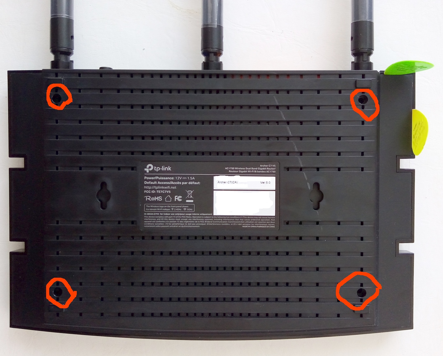
With the screws removed, I used my trusty guitar picks to start opening a gap in the position you see above (corner near the antenna). As much as the screws would actually be sufficient in keeping the device together, manufacturers all seem to have fallen in love with permanent locking tabs, so when prying with the picks I’d have to create enough space to free each tab. Being careful while working around, I was able to do it without breaking any tabs (my old Archer C2 had less than a 50% survival rate).
I worked down the side, across the front, and up the opposite side, saving the rear with the antennas for last. In addition to being careful with the antennas, I had to be careful with the circuit board which becomes loose as you open it up (the screws normally secure it’s position).
Once the sides and front are free you can actually open it up enough to see the location of the uncooperative rear center tab. At that point I just stretched the unit open expecting that final tab to break – it survived.
The Archer C7 (v5) circuit board
TP-Link’s C7 has actually been around for a few years and has undergone a number of revisions. This one (version 5) was the latest. Despite searching before buying it, I was unable to find any pictures of the v5 circuit board. Here it is:
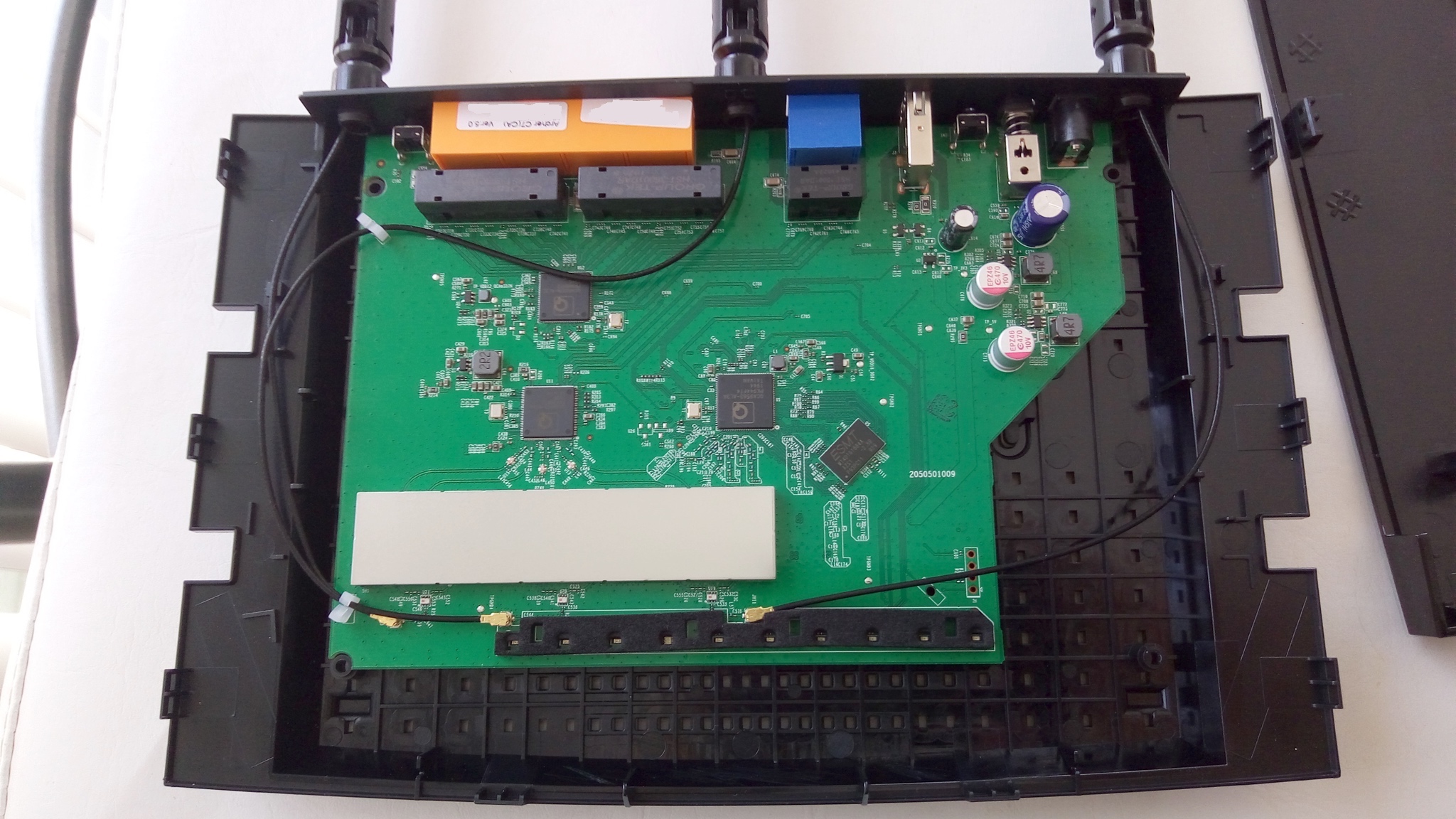
Having seen many pictures of v1 which had many no-name electrolytic caps, I was impressed by what I saw in version 5. Two of the four capacitors were polymer caps! Layout was nice and clean too.
Side-note: For those who may want to replace the capacitors with some brand-name options, these are the included capacitors:
- 2x EPZ46 10V 470uF 105˚C (polymer)
- 1x JWCO 16V 220uF 105˚C
- 1x AiSHi 25V 740uF 105˚C
I checked the rear of the board and there’s actually ample room around the capacitor solder points. If planning to hard-wire in a 5V fan, note that room around the USB solder points is quite a bit tighter but should be reasonable if you’ve got a steady hand.
With the initial inspection complete, it was time to start figuring out what degree of modding I was going to do here.
Quick “does it get hot” finger-feel Temperature Test
With the board exposed, I powered the thing on and ran iperf from a machine on the 2.4Ghz network to an ethernet connected one just to get a rough idea as to what temps might be like with some light activity.
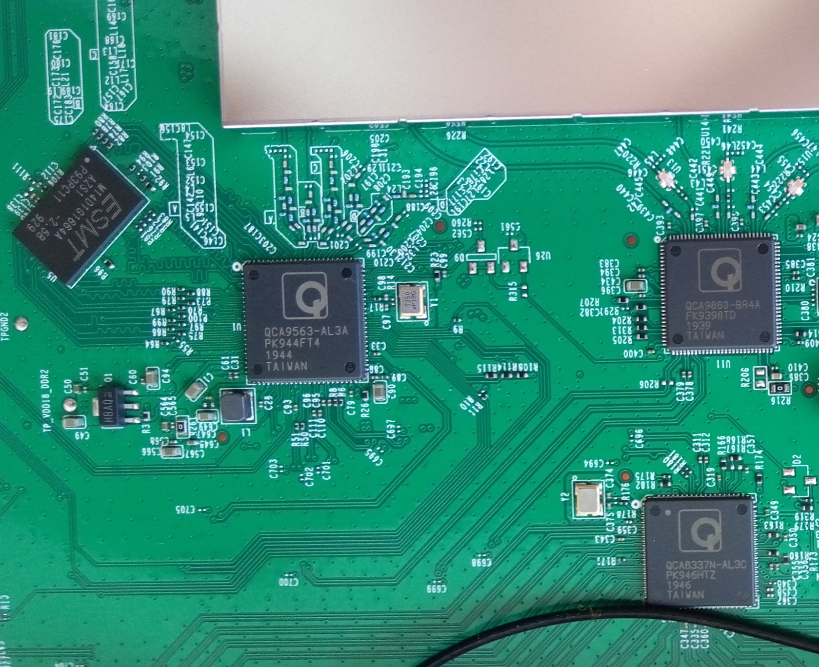
I touched every chip that was feasible to touch, with a focus on the 4 main chips seen above. These are:
- QCA9563-AL3A (center-left, main SoC and 2.4Ghz)
- QCA9880-BR4A (upper-right, 2.4/5Ghz)
- QCA8337N-AL3C (bottom-right, 10/100/1000 Ethernet)
- ESMT-M14D1G1664A (top-left, RAM)
They all felt lukewarm. The RFI shield at the bottom of the circuit board actually felt warmer.
I pulled out the temperature gun and ran it across the board. I was hitting around 30-35˚C with a peak somewhere of 39˚C. These chips did not seem to be getting very hot, though the cover was obviously off so they had the advantage of free air. The RFI shield was on the warm side, but I figured it was probably acting as a heatsink for components below.
However, after powering the thing down and lifting the router, the rear plastic felt quite warm on the opposite side of the RFI shield. Ah ha!
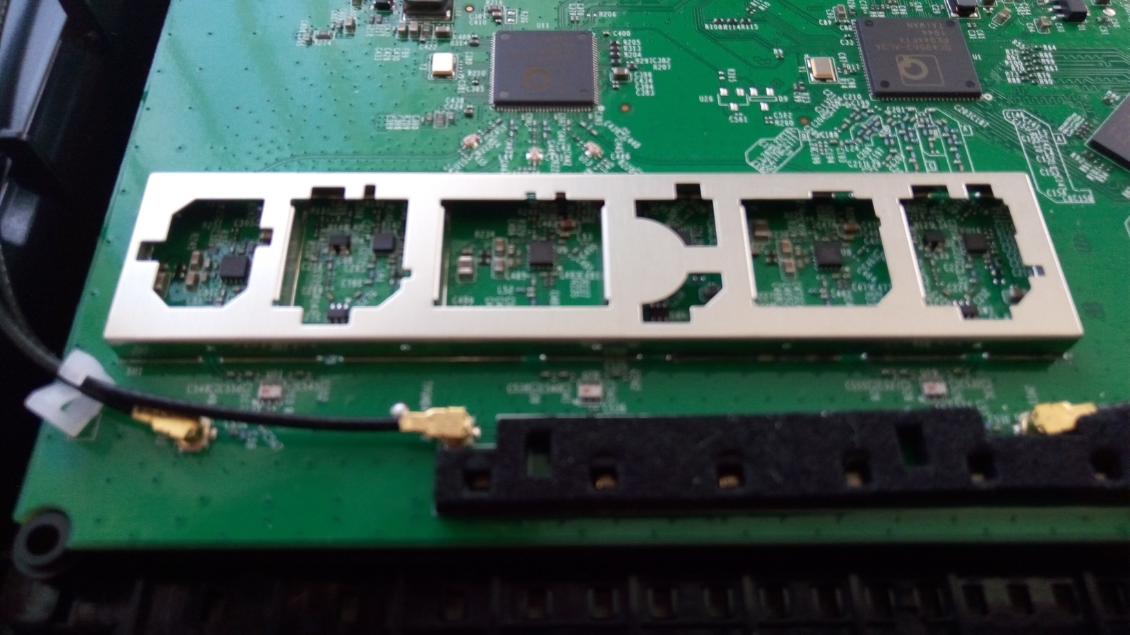
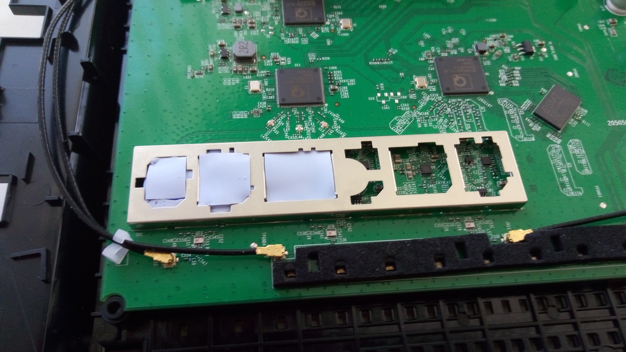
Looking behind that RFI shield
With the rear plastic being warm behind the shield, I started to think “maybe the components inside aren’t actually sinked against the cover….”. It was worth a look. Unfortunately my initial attempts to pull the shield up with fingernails didn’t get me very far.
Having yanked a spade connector right out of a UPS motherboard the day before, I was hesitant to use too much force here. After all, I could just install a fan… there were slight air spaces where the motherboard traces exited the shield and some air would probably make its way though if a fan were well positioned.
A fan would definitely be the prudent, safe thing to do.
Problem was I didn’t have an extra fan around. So….
For anyone bold enough to try and force the cover off… maybe look around a bit first to see if there are safe tricks/methods other people use. In retrospect some heat would have probably helped. What *I* did was put a guitar pick on the PCB to the right of the RFI shield (up against it) since that area was free of components. The guitar pick was the “PCB protector”. Then I took a sharp flat screwdriver, put it between the cap lip and guitar pick, and starting rotating the screwdriver to force the cap to start coming up. Once up enough, I used a slightly larger screwdriver to get it the rest of the way.
Since the shield/cover is “sectioned”, once I had that first section up, I just ripped the rest of the cover up by hand: the cover ended up “banana shaped” but it was easy enough to bend back straight.
Note that the base was really well soldered to the PCB. A good thing, because it took a lot of force to get that darn cover off.
In any case, at least 1 of these chips (probably a few) were obviously heating up a fair bit. Trying to heatsink them was out of the question, as there’s little space, some chips are hard to get at, and the RFI shield would still be acting like a little incubator anyway.
Examining the options I had available, I came up with 2 possibilities to try and alleviate the situation:
- Option 1: Fill the entire thing with thermal paste. Pros: Easy. Cons: Lots of paste required, some may squeeze out the bottom. Unsure of the thermal conductivity of paste when lots is used, unsure of shrinkage over time as it dries. If it’s at all electrically conductive I’m in trouble.
- Option 2: Cut up some thick thermal pad and start layering it in there. Pros: Guaranteed not be electrically conductive. Is already thick, so designed for large spaces to at least some degree. Cost effective compared to all that paste. Removable. Cons: Time.
I decided on the thermal pads since I had some thick stuff laying around. It took a lot of cutting and coaxing, but I eventually got 3 layers in each compartment.
Since I didn’t know whether the cover actually sat “flush” with the top, I made sure to have a little extra pad sticking above: just enough that it could still compress if the cover were flush without breaking any of the chips below.
Once that was complete, I decided I may as well put some horrendously thick “beads” of thermal paste across the top just in case the cover really wasn’t flush. Also, the chips below prevented my pads from being exactly level.
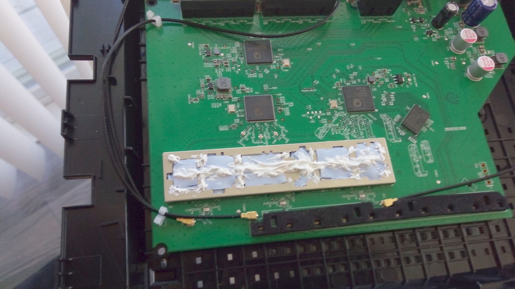
I half expected all the paste to just ooze out like crazy when reinstalling the RFI shield cover. Surprisingly, only a tiny bit actually did. Either the cover wasn’t flush or the paste all oozed down inside somewhere. Either way, this part was done.
With that complete, I figured I may as well heatsink everything I could.
Quite some time ago I had bought a little package of cheap teeny heatsinks from eBay that are great for small chips and low clearances. Since the main Qualcomm/Atheros chips weren’t very hot to begin with, I figured the teeny heatsinks would do nicely.
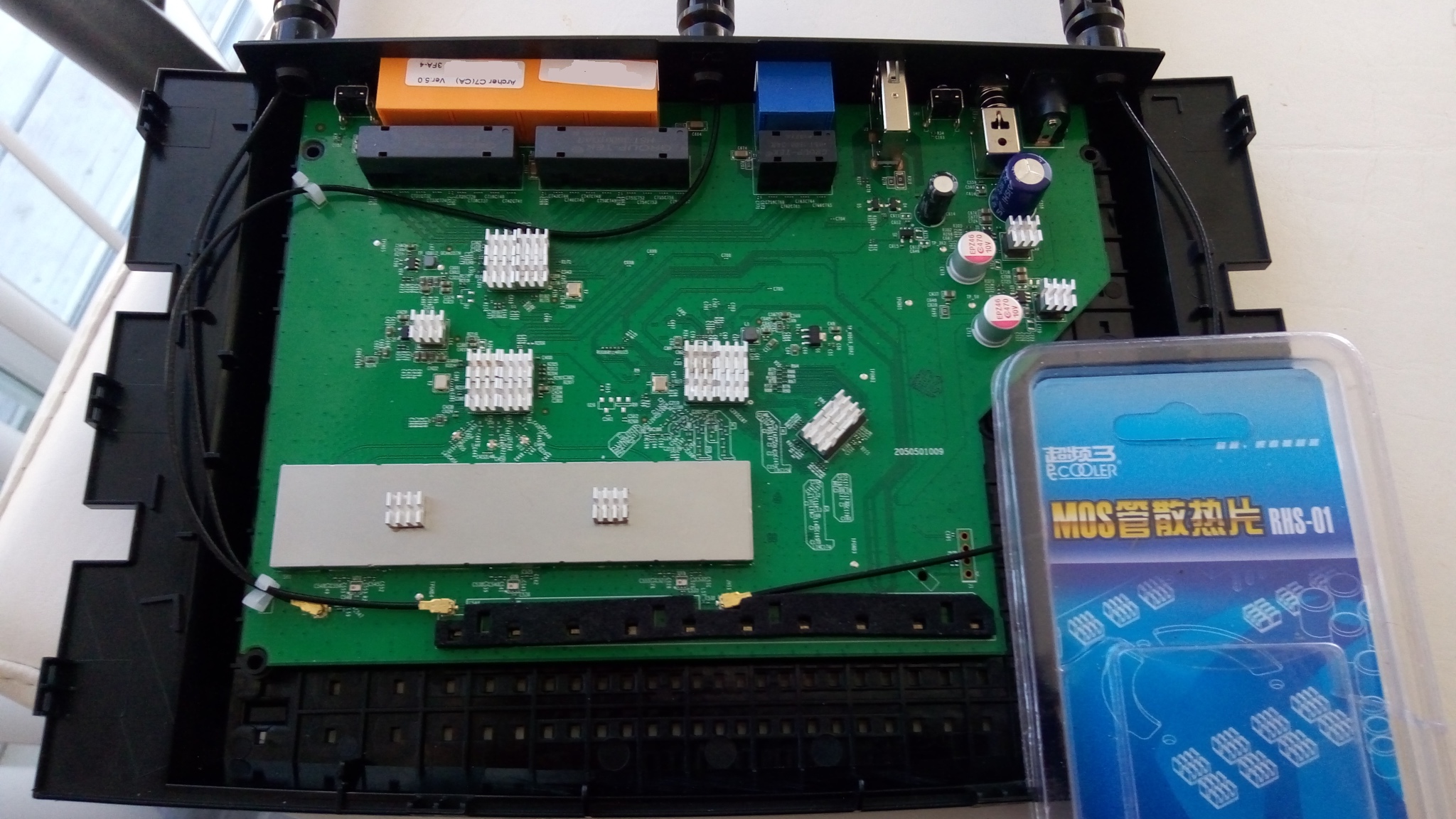
Since I had a few heatsinks left over and wasn’t adding a fan, I put some on the other components as well. They weren’t warm by any means, but the hope was that with those being taller components, any heat conducted through the PCB in those regions might end up there and reach a heatsink. Trying to put heatsinks on the really small stuff seemed a bit risky due to nearby component heights and the resulting risk of shorting.
As a note, if you’re looking for these teeny heatsinks, they’re easily found through the common channels (Amazon, eBay, AliExpress, etc). They’re handy for lots of odd little components.
Final Testing and Conclusion
I re-assembled, re-powered, and ran iperf again to try and get a little heat generated. This time the bottom plastic was much cooler below the RFI shield, to the point where the space below the left side of the circuit board (the regions near the 2R2) was now the warmest!
–
Overall, I was pretty pleased with the stock router even before modding. These Qualcomm chips seem to be pretty efficient (little heat), polymer caps were a nice surprise, and the thing wasn’t too terribly painful to open up compared to most other stuff that utilizes permanent locking tabs.
The biggest downside seemed to be the components under the RFI shield. They obviously got quite warm and were pretty hard to access. Yes, the hardest thing to mod was the thing that seemed like it would benefit from modding the most! In any case, hopefully the thermal pads increase their lifespan from whatever-they-would-have-been to something a good bit higher.
I would never have thought to refresh the thermal paste on my router!
I just gave it a go and now it runs like a brand new piece of kit!
This Archer C7 model comes in the following versions V1 and V2 and V3 and V4 and V5
which version is the best ?
As to the stacked pad concern, given that the area below the shield was cooler after the pads were added, it's probably safe to assume the pads weren't insulating in the beginning. If the pads or thick gobs of paste I put on started to dry out over time, I suppose that could change though. They do however have the benefit of not being exposed to airflow, and the heat load they take is less extreme than in many other common applications.
With all that said, it could have very well have lasted the period of use even without the modification.