Following up from my previous post, it was time to replace the thermal paste on the CPU/GPU on the Samsung NP-Q460 laptop (known to Best Buy and Future Shop as the Q460-JS01CA in Canada) to see if I could reduce temps.
It involves some fairly major disassembly. Worth noting a few things before we get started here:
- The Q460 is one of the harder notebooks to disassemble. There are many plastic clips and you’re going to have to do a lot of careful prying.
- Even if you’re careful, you may end up with some cosmetic damage around the case seam, particularly if you use a sharp object to do the prying. Oh, and you’re probably going to have to use a sharp object to do the prying.
- I didn’t see gains by replacing the paste (details at the end). YMMV of course.
- This will probably void your warranty. You’re doing this at your own risk. If you’ll be extremely sad/mad if you break the system, and/or you’re not comfortable doing this, you probably shouldn’t attempt it.
—
So, let’s get started!
—
STEP 1 – the easy stuff (you probably haven’t voided your warranty just yet….)
Click on the image below for a larger version.
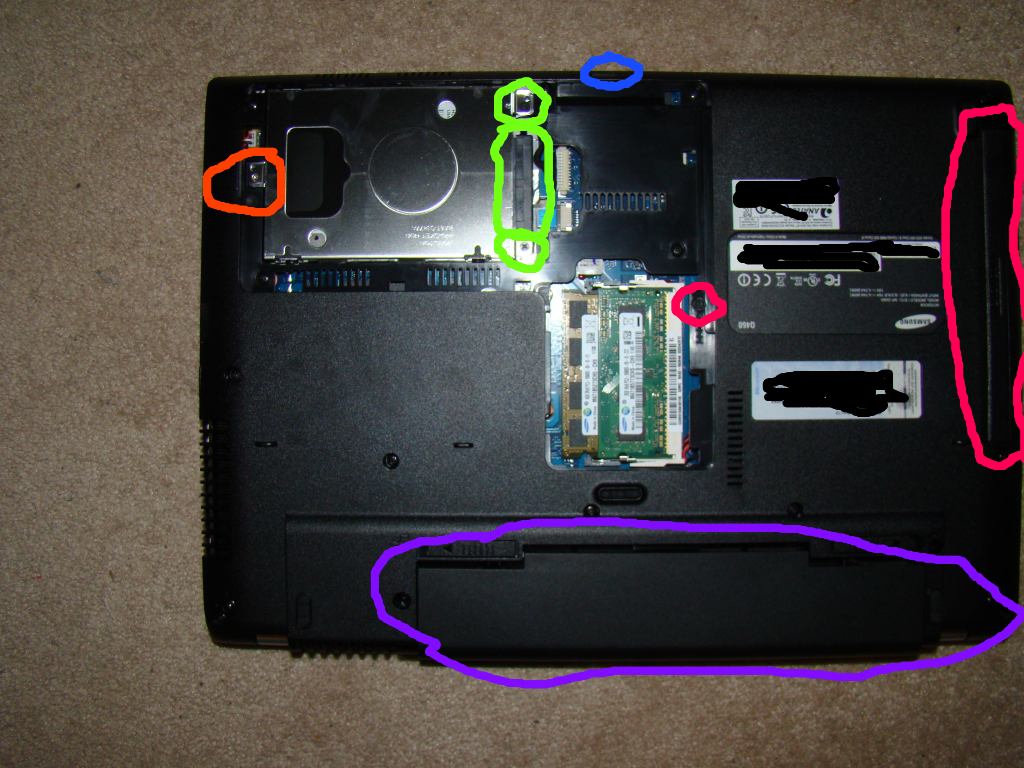
You’ll see I’ve already removed the access panel. It’s removed by taking out the screw in the orange location, and carefully prying it out from the clips.
Purple – The battery. You should probably remove this before doing anything unless you’re hoping for a spark show when you slip with the screwdriver (2 spring clips, covered in the manual).
Orange – This is where the access panel screw was. In my previous post, I mentioned they overtightened mine at the factory and I had to use a dremel to cut a new slot. Hopefully you have better luck.
Blue – The “blank” in the memory card slot. Slides right out.
Green – Remove the remaining 2 screws that secure the hard drive, pull the drive out slightly, and slide off the SATA connector/cable.
Pinkish/red – 1 screw (a little smaller than the others) holds in the DVD drive. Once you remove it, slide the DVD drive out.
STEP 2 – A mess of screws (don’t lose them!)
Click on the image below for a larger version.
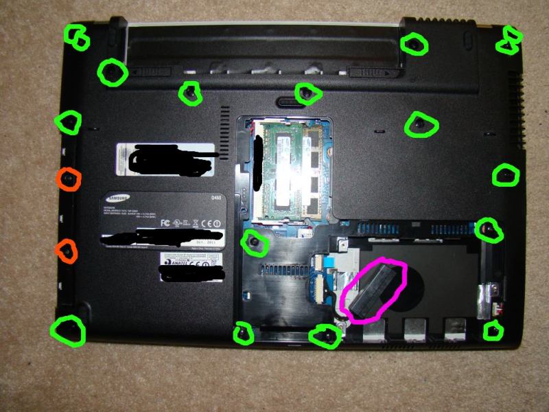
You’re essentially removing every screw you see.
Green – Most of these screws are the same size, though you should try to keep them separate so you’re able to put each back in it’s original place anyway. None were very tough to get out with a standard philips screwdriver. While I think I labelled them all, it’s possible I’ve missed a couple in the above picture, so if you see one that isn’t shown, you may need to remove it – fortunately, they’re all pretty obvious.
Orange – These 2 tiny screws are located where the DVD drive was before. They’re tiny, so don’t lose them. They can also be a pain to get out – mine were overtightened at the factory. I had to attach a vicegrip to a tiny screwdriver to get the torque I needed to crack them loose. One hand turned the vicegrip while the other pushed down the screwdriver to keep the screw from stripping. If you manage to strip the screw, you’re probably going to have to use a dremel to cut a new slot or drill the head off the screw and try to remove the shaft later.
Pink – this is the hard drive SATA connector from step #1. You don’t have to do much else, but remember it. It gets in the way later when you try removing the bottom of the case, and will get in the way when you try reassembling it.
—
Step 3 – Removing the bottom panel (unclipping the clips). AKA “the worst part”
This part sucks.
Click on the image below for a larger version.
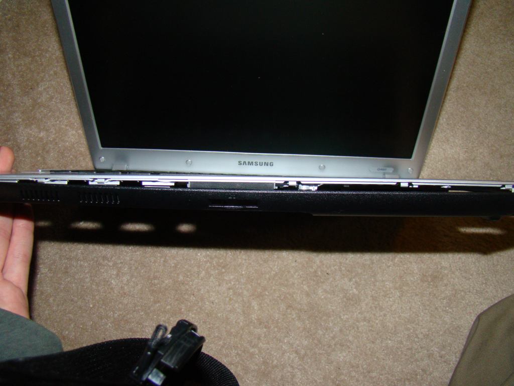
I found it easiest to start at the front. Open the screen/display a bit.
The way I went about this was using a thin, sharp knife. I stuck it between the silver/black at an angle, and pryed the black “away” from the clips, working my way around slowly. As you get some of the clips disconnected, you’ll probably have to use 1 hand to keep them from popping back in.
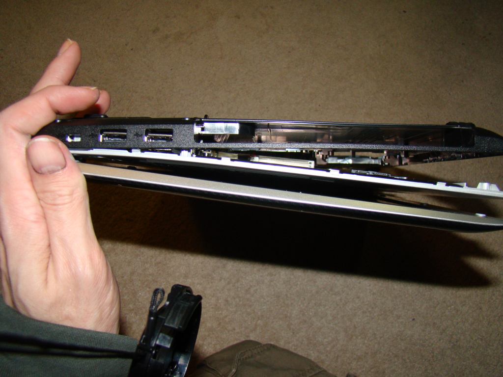
Next, I worked my way around the sides, going from the front of the machine towards the back, working both sides at a time. The side you see above was the “easier” side. That said, prying the clips near the DVD drive location was a little tough – the plastic is really thin and I worried it would crack before the clips came.
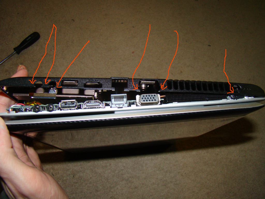
The side above was a pain (again, click on the image for a larger picture). The problem is that not only do you have to pry the black plastic away from the clips, but it catches the microphone, headphone, VGA, and power connectors. You have to pry the black plastic away from them too. I put orange arrows at the trouble-spots.
The power connector in particular is a huge pain – you have to pry an awful lot to get the black plastic over it.
—
Once I got the the front/sides unclipped, I simply pulled the black case bottom up, it pivoted, and the rear clips came un-done on their own.
STEP 4 – The guts of the machine (getting easier again!)
Click on the image below for a larger version.
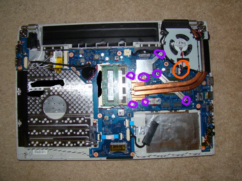
With the panel off, all we’ve left to do is remove the CPU cooler and heatsinks. It’s all 1 piece (I’d incorrectly guessed the CPU and GPU had separate heatsinks in my previous write-up)
Purple – Remove the screws for the heatsinks. Generally, you want to unscrew all of these a little bit at a time so that you maintain even pressure on the chips. Give 1 screw a turn, give the next screw a turn, etc. Go back to the 1st and repeat.
Orange – This connector is for the fan. It should pull out easily, but it doesn’t. I had to use a small screwdriver to gently pry it out of it’s fitting a bit at a time.
Once everything’s removed, it should lift right out.
—
STEP 5 – the heatsink paste
Click the image below for a larger version.
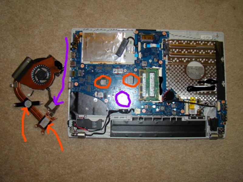
Here you can see the existing thermal paste. If you’re replacing the paste and haven’t done it before, you may want to read the many guides on the web elsewhere before continuing.
Orange – The CPU and GPU locations. Surprisingly, the factory stuff was already fairly thin. Some excess had squeezed out the sides, but for a factory-job, it was pretty decent. I cleaned it off with rubbing alcohol and used Artic Silver Ceramique as the replacement.
Purple – The thermal pad on the chipset. I would not suggest replacing this with paste, as it won’t be as thick as the pad and probably won’t make good contact (if any). Leave it alone unless you’ve got a mod in mind.
Maybe I just got lucky, but the clearances machined into the heatsink for the GPU and CPU were nearly perfect. I applied a small amount of paste to each chip, temporarily reattached the heatsink, and both transferred perfectly. +1 to Samsung for this. That said, make sure you temporarily attach the heatsink and check for paste transfer in case you weren’t as lucky as I was.
—
STEP 6 – Reassembly
Unsurprisingly, it’s the opposite of removal. A few things to note though:
- The hard drive SATA connector I mentioned earlier…. if you’re reassembling now and the case just won’t go back together, it’s probably in the way.
- Remember to pry the plastic back over the power/sound/mic/VGA connectors.
- Assuming both the above aren’t causing you problems, it snaps back together quite easily. Once I got it started, I was able to pretty much put the thing on the floor, push down, and everything snapped back into place.
When the machine is back on, you might want to run a couple temperature-monitoring programs just to make sure everything looks good. RealTemp is good for testing the CPU, and the monitoring section of GPU-Z is good for testing the GPU.
You may also want to run some stress testing programs while monitoring the temperatures carefully. If you messed up and things are overheating, it’s better to find out right away (while you’re monitoring the temps) than it is to have something burn itself out a week later.
—
RESULTS
To put it simply… there weren’t gains, at least under load. Here are the numbers:
GPU
Before: 79 degress (load)
After: 78 degrees (load)
CPU
Before: 81 degrees (load)
After: 83 degrees (load)
Basically, the GPU was 1 degree cooler, and the CPU was 2 degrees warmer. Both pretty much within the margin for error. No real change to speak of.
–
A few possible reasons for this:
- The Arctic Silver Ceramique I used – the tube’s well over 5 years old (it’s all I had available where I am at the moment). It’s known to result in temps a couple degrees higher than other more-recent thermal pastes. It’s thicker, and I certainly didn’t manage to spread it as thin as I can with other pastes. It may also need time to cure (temps could very well go down in a few days).
- Application – while it looked pretty good, I may have used more/less than necessary.
- The original paste Samsung used might have been just as good as anything else.
In any case, time will tell. I may disassemble the machine again later and try some other paste.
–
CONCLUSION
For being quite the pain to disassemble, it’s a little disappointing that there weren’t temperature gains to be had this time around. It’s possible that a few mods to the bottom panel might help airflow, but it’s something I’ll look at another time.
In any case, if you need to disassemble your system, hopefully the guide has helped you. If you’ve attempted this and have any tips of your own (or replaced the paste and saw better results than I did), feel free to leave a comment below!
How does this laptop rate for battery life ? I ask because I'm currently looking at this Samsung and an Acer.
Samsung : http://ncix.com/products/?sku=67870&vpn=NP-Q460-JS01CA&manufacture=Samsung&promoid=1215
Acer : http://ncix.com/products/?sku=64643&vpn=LX.RGL02.082&manufacture=Acer
They are both the same price here in Canada ($699 CDN), but from what I've been able to glean on various boards, the Acer has up to 9 hours of battery life out of the box (over 6-7 hours of light browsing on wireless).
Hopefully someone else can chime in - I haven't run the battery down yet (to be clear: not because it's super-awesome, just because it's almost always plugged in).
ah, and have you gone round to putting new DDR ram?
I was playing around with one in memory express on display, reserved it for the day, I have until tonight to buy it 649cdn
the nvidia drivers controlling the switching between discreet/integrated probably can be 3rd party tweaked/modded to auto switch at different load% , having to set the programs in the driver seems like a pain. How well does skyrim play on it?
none of the USB ports are 3.0 right? I got confused with device manager showing a USB 3.0 device host but no ports?
and saw one of the Samsung utilities indicate a always-on USB port function for charging something when the laptop is off, but couldn't make out which port that'd be
eek, looks like I'm a day or two late - maybe the response will aid someone else though...
I actually did have it apart again (swapped to a US-style keyboard) and replaced the thermal paste with some Arctic Silver at the same time. Unfortunately, I didn't take before&after temp readings the second time around.
I'd also replaced one of the 2GB sticks with a 4GB stick (so it's got 8GB RAM total vs 6GB RAM previously). It was RAM I happened to have lying around. At some point I might look at replacing those with lower-voltage-ram - Samsung actually has some decent looking stuff on newegg in that area. The notion is that perhaps it'll drop temperatures slightly, extend battery life (the few times I'm actually on battery power), etc.
I haven't played Skyrim on it - spent a very short period of time playing SW:TOR though - I went with the lowest graphics options @ native resolution and it flew at around 60fps most of the time. I didn't bother trying to turn anything up because the screen is so small that I doubt I'd be able to tell much of a difference.
As for having to control the graphics switching, I didn't need to. It automatically switched to the nVidia chip when I popped open the game. I played around with it some too, and note that rather than using nVidia's control panel to set the graphics mode for a game (should you need to for whatever reason), you can instead right-click the icon for whatever game/program you're going to run and choose between Intel/nVidia in the context menu. Again, I didn't actually need to do this - I was just messing around.
None of the ports are USB3 as I recall.
Do you remember if the CPU is soldered to the board on this laptop?