After a couple weeks of less-than-usual power generation from my solar panel array, I decided to pull out the ladder and start testing panels. Turned out, the Coleman string was dead.
Voltage read fine, but a current test showed 0 amps.
Great.
I narrowed it down to 1 of the 2 Coleman panels, unmounted it, and lugged it down the ladder to take a closer look, thinking “it’s either the diode or a toasted cell…. please be the diode…”.
Turns out, the diode was dead. Really dead. Massive-crack-running-through-it-dead.

You can click for a larger image.
The good news:
- The catastrophic diode failure was nice and visually obvious. No guesswork here, and no need to actually test the diode. If only all components failed so spectacularly!
- It’s a fairly simple fix.
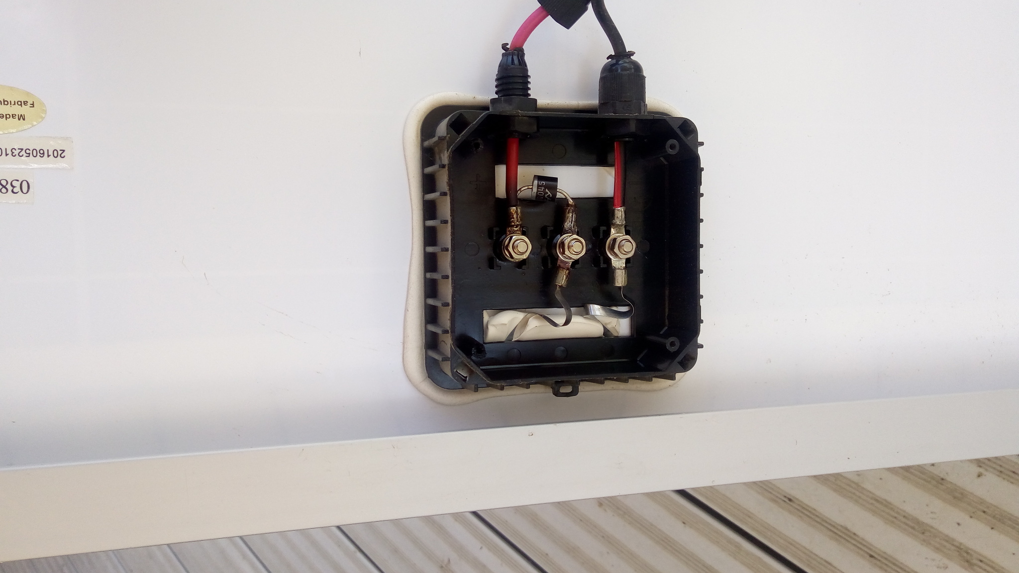
You can see the replacement diode installed above in the black box located at the rear of the solar panel (4 small philips screws to open).
If you have a replacement diode and are handy with a soldering iron, it’s a pretty straightforward fix. Pull the 2 nuts, slip off the wires, slip off the diode assembly, de-solder the old diode from the ring connectors, and solder the new one in. Be mindful of the diode orientation (white/grey strip on the diode goes to the positive wire here).
If you have a replacement diode but are not handy with a soldering iron (or are lazy), after you have the old diode out, the leads on the new diode are probably long enough to curl around the threaded shaft, so if you’re careful you can probably get it in place and tighten the nuts enough to keep things together. Again, be mindful of the diode orientation (white/grey strip on the diode goes to the positive wire here).
If you don’t have a replacement diode, you could skip the diode to get the panel working for the short term. Either use a jumper wire where the old one was (to connect left to center), or move the “tabbed” wire from the center peg to the left peg (connected directly to the red positive wire). The down side here is that without a diode, your battery/etc may discharge into the solar panel at night which isn’t so good… if you’re using an array of panels you could run into other issues here too. Really, a diode (known as a “blocking diode” here) is installed to make sure power only flows out of the panel and not into it! So at the very least, if you’re skipping the diode, disconnect the panel from whatever it’s hooked up to in the evenings until you get a diode.
As for what diode to use, most of these panels seem to come with standard run-of-the-mill 10A 1000V diodes (10A10 diode in this one), However, if you want to increase the panel voltage slightly (up to half a volt or so), and reduce power wasted in the diode, you can look at using a “Schottky” diode. They’re more efficient but you can’t get them in really high voltages. I used a 10A 45V Shottky, but as long as whatever you get has a minimum current rating of 6A or so (realistically you’ll find a 10A), and a minimum voltage above the peak your panel will see (say… 25V if you’re just using single panels on a battery, 45-50V if 2 panels in series with only the final panel w/diode, etc) you should be good. If you’re doing something really exotic you might need something with a higher voltage, but for most of the common use cases you shouldn’t.
–
The final result:
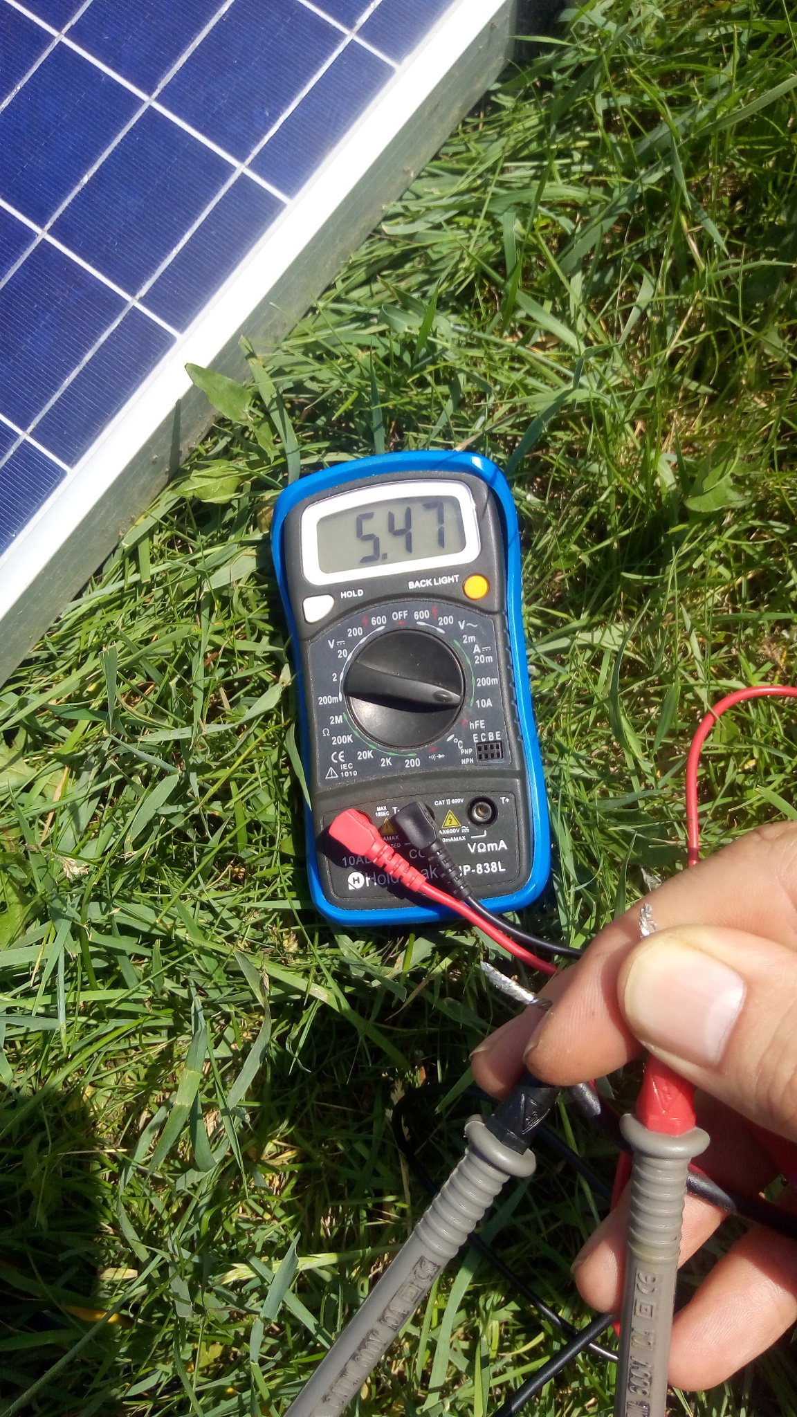
Over 5A short-circuit current with some decent sun.
All was now well! Panel went back up, and power is back to where it should be.
If you are connecting the panels in series, you could remove all but one diode to reduce the forward voltage drops and still have the reverse voltage protection, you only need one diode in the series connection. In parallel connections, you need a diode for each panel to keep a panel that is "shorted" from affecting the output of the rest of the panels.
That way you can mount it on a heat sink and it will never fail again.
"Voltage read fine, but a current test showed 0 volts"
I think you meant "...showed 0 amps"?
That is the exact failure I have - volts (Voc) are as expected yet amps (Isc) are 0 (sadly, now on 5 of 8 panels and getting worse). What I'm trying to understand is how this can happen... If the diode is shorted, I would expected to have seen lower Voc (as one section would be removed, so in a three section panel I would expect to see 2/3rds the voltage). If the diode was always open, then it would have normal amps (short circuit, Isc) but no bypass protection (draining battery, shaded cell, etc). It seems the only way this condition can occur, and the problem being the bypass diode, is if it still conducts at very low current, but breaks any high current. Did you ever test your cracked diode? I'm hoping the problem is a defective batch of diodes as that I should be able to fix - but I can't visit the panels right now (they are on a boat not near me).
Also - and maybe I misunderstand - but in your 2nd to last paragraph (if you don't have a replacement diode) you said "Either use a jumper wire where the old one was". I thought this would short out the segment and result in 2/3rd Vcc and 2/3rd Isc? Removal of the diode (and not jumping it) I had thought would have the desired effect.
I'm no expert on this topic - just doing a crash course to understand my failure, so I may be all backwards!
In this case, this diode isn't a bypass diode - it's just for reverse polarity protection. If you look closely at the image it will make a little more sense since you'll see the +/- "tabbed" wires from the panel array (bottom) and the +/- output wires (top). The lugs/nuts aren't connected to anything internally and are just there so you can electrically connect the 2 tabs to the 2 output wires. If you were to only remove the diode (and do nothing else), you'd have nothing connecting the positive panel tab to the positive output wire and would be open-circuit.
To think of it another way, if they didn't bother with the diode, there would only be 2 lugs/nuts - 1 to join the positives and 1 to join the negatives.
Hope that makes a little more sense!
They produces ~18V. They are connected in parallel in the following setup:
Each panel is independently connected to it's own controller charger and then each output from the controller charger are connected together in parallel.
My system was working well charging at ~14.2V but yesterday I read the output voltage and it was on 18V. So I kept it disconnected...
Is this normal? What could be happening?