After trying various MPPT and PWM controllers for batteries, inverters, testing, etc., I decided the best use of the wind turbine was going to be as a hot water heater. Initially I’d tried a few elements at various resistances, but the (obvious) issues here bothered me a bit too much:
- If the resistance is too low, the wind turbine can pump lots of wattage into the element at high winds, but it has trouble starting at low wind speeds.
- If the resistance is too high, it’s easy to get power in low winds, but windy days become a problem and you need to throw the excess power somewhere as the voltage skyrockets.
The solution: a low resistance element, driven by an Arduino and MOSFETs.
First a picture of the end result:

<“it wouldn’t win a beauty pageant?! it’s whats on the inside that counts!” comment goes here>
Okay, so it’s not a looker. And it’s not MPPT (I’ll go into why later). But it varies the load based on the voltage and works swimmingly.
I’ll start with the purpose, move on to the “how”, and end with a couple tidbits of code in case you’re aiming to do something similar.
The Intent and Purpose
As I alluded to earlier, a low load works great at low wind speeds and a high load works great at high wind speeds. After all, when the wind is a slight breeze, you want the wind turbine to spin and generate something. A resistance that looks like a dump load isn’t so good. On the other hand, when winds are so insane that you’d normally need a dump load, hey… at 100% duty cycle that heating element is a dump load!
More specifically I wanted the following:
- At tiny wind speeds (up to about 5v unloaded), no load put on the turbine. Let it turn.
- At low wind speeds (up to about 12v unloaded), place a light load on the turbine. As you can see, it’s pulling under a watt in the picture (no real wind – I picked a great time to take a picture…). And sure, that’s pretty much nothing. But I’d argue that 0.9w is still slightly better than nothing.
- At medium wind speeds, start pulling more. Say around 100w at 12v loaded.
- At higher wind speeds, directly connect the element (100% duty cycle).
I also wanted to be able to tweak these values easily with code. Maybe start at 3v instead of 5v. Maybe go full load at 18v instead of 24v. Room to experiment and room to make changes when I swap the 7-blade wind turbine assembly in again and want to pull a little more power at the lower voltages.
So putting together something that could do this was the goal.
The How
Okay, so a few critical components:
- The Arduino Uno (Mega may be smarter if you want to do something fancy)
- MOSFET(s) – I used the N-Channel HUF76137P (75A 30V) but find something that’ll handle your current and voltage and is switchable with the Arduino’s meager power output.
- Resistors – for voltage dividers (in addition to current limiting the MOSFETs and other menial tasks). You want the voltage dividers to take the max possible voltage the turbine will ever output and bring it down to 5v so that the Arduino can handle it.
- Whatever heating element you’re going to use. Low enough resistance and high enough rating to handle whatever your turbine can throw at it.
That’s really about it. Display (as seen) is nice, If doing something similar, I’ll assume you have a bridge rectifier, wires, thermostat (if using one), etc.
As for wiring, mine kind of resembles this:
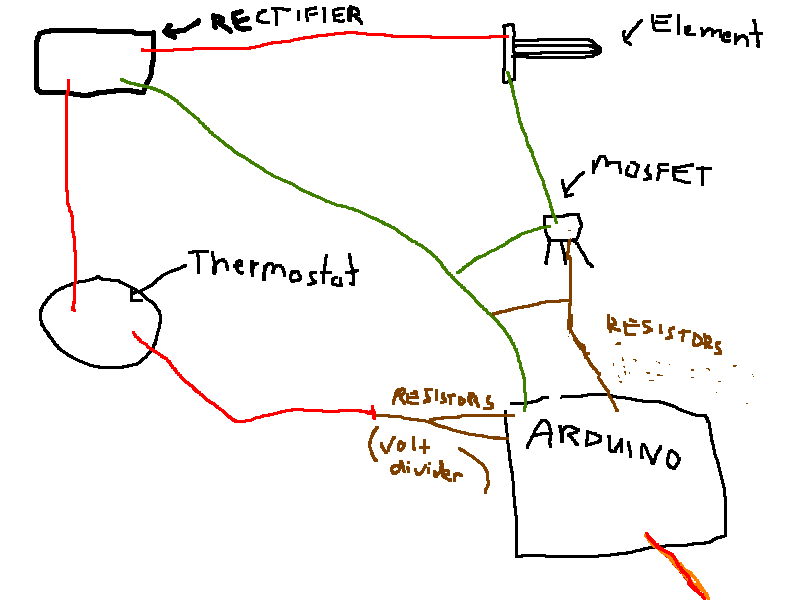
- Green are the ground wires.
- Red are the positive wires.
- Brown are resistors – the ones going to thermostat are voltage dividers which go to the analog input on the Arduino. The ones going to the MOSFET (splitting to ground) are from the Arduino PWM pins – the resistors are to current limit the MOSFET and to let the MOSFET turn off fast by having a path from the gate to ground.
- Note that this is for an NPN transisitor (it feeds the ground). If you were to use a PNP transistor (feeding positive to the element) it would be wired differently.
- Note that the Arduino is powered separately, but you’d need to tie into the ground from the rectifier also.
Consider this diagram an overview. It’s just to give you an idea as to what the overall picture looks like, but you’ll want to design something around whatever you intend to do. For example, if doing something similar, you’d want to calculate your own resistor values for both the divider and to the MOSFET to jive with whatever surge current limiting you want.
The code logic I went with looks like this:
- Read voltage (through voltage divider which should give max of 5v) and multiply to get original voltage
- Plug voltage into equation to get the desired power output in watts
- Calculate the actual output power if direct-connected to the 1-ohm resistor (P=V^2 / R)
- (desired watts) / (actual watts if direct connected) = duty cycle to use
- Convert duty cycle(0.0-1.0) to the (0-255) range
- Apply that duty cycle
I used a bench power supply when iterating through the program to make sure everything worked as expected and output all the values to the Serial Console as I made changes. First made sure voltages were read correctly, then code for the calculated and intended watts, then code for the duty cycle, etc.
Some Sample Code
A couple tidbits that you may find interesting or that may help if you’re (again) doing something similar and are wanting to see how I went about it:
//This one will be hard to read. BASICALLY it reads the voltage (from the voltage divider).
//To "smooth" the voltage, it then stores it in an array and takes the average from that array.
//It then checks to see if the average voltage has changed. If not, it does nothing. If it
//  did change, then it runs LOADTABLEVALUES() which is in the next code block and does the
//  actual work of figuring out power/PWM/etc. After LOADTABLEVALUES() is run it changes the PWM.

 void a0load() {
  unsigned long starttime = micros();

  a0current = analogRead(A0);

  a0runningtotal -= a0values[a0valuescounter];
  a0runningtotal += a0current;
  a0values[a0valuescounter] = a0current;
  a0valuescounter++;
  if (a0valuescounter == AZERO_VALUES_ARRAY_SIZE) {
    a0valuescounter = 0;
  }

  a0runningavg = a0runningtotal / AZERO_VALUES_ARRAY_SIZE;
  if (a0runningavg > a0prevavg+1.1 || a0runningavg < a0prevavg-1.1 || (a0runningavg < 0.02 && a0prevavg >= 0.02)) {
    a0voltagechanged = true;
    if (a0runningavg < 0.02) {
      a0runningavg = 0;
      a0current = 0;
    }
    // unsigned long timetaken = micros() - starttime;
    //Just in case voltage is somehow out of range, make them in-range and int-castable...
    if (a0runningavg > 1023) a0runningavg = 1023;
    if (a0runningavg < 0) a0runningavg = 0.001;

    //Preps tablevoltage (f), tabletruepower (f), tabledutycyclecalculated (f), tabledutycycleactual (f), tablepwmvaluefordutycycle (int)
    loadtablevalues((int)(a0runningavg));

    if (tablepwmvaluefordutycycle != pwmvalueprev) {
      analogWrite(9, tablepwmvaluefordutycycle);
      pwmvalueprev = tablepwmvaluefordutycycle;
      a0pwmchanged = true;
    }


//    float thevoltage = (a0runningavg * 7.93 / 1024 * 5);
//    Serial.println("Vnum: " + String(a0runningavg) + " - " + String(tablevoltage) + "v. Took " + String(timetaken) + " micro seconds" + " Watts: " + (tabletruepower) );
    a0prevavg = a0runningavg;
 //   Serial.println("delta " + String(deltatime) + " prevmicros " + String(prevmicros) + " currmicros " + String(currmicros));
  }
Note that most variables were assigned elsewhere – this *might* be an example worth looking through to understand. But this probably isn’t an example you want to actually copy/paste.
//This section is shorter and easier to follow. It takes the voltage we read previously and
//figures out what PWM to apply.

//Takes 412-432us to complete (under half a millisecond)
void loadtablevalues(int inputvltvalue) {

  //TESTING:
  //unsigned long starttime = micros();

  float tableresistorpower = 0;
  //Some different equations I tried.
  //(0.043)x^3
  //new: 0.043(x^3)-4
  //new again: 0.0545(x^3)-40 very low load, 0 starts at 9.25v, 100% starts at 20v (20v*20a=400w)
  //newer: 0.0502(x^3)-2 , 0 starts at 3.3v, 50% load at just over 10v

  //Converting from ADC number to voltage.
  tablevoltage = 1.0 * inputvltvalue * 7.93 / 1024 * 5;

  //The cubic calculated power.
//  tabletruepower = 0.0502 * pow(tablevoltage,3) - 2;
  tabletruepower = 0.3502 * pow((tablevoltage-5.0),3);
  if (tabletruepower < 0) tabletruepower = 0; //The power demanded if turbine connected directly to resistor (100% duty cycle): P = V^2 * R, used to calculate power at 100% PWM
  tableresistorpower = pow(tablevoltage,2) / RESISTOR_OHMS;
  if (tableresistorpower > 0.001) {
    tabledutycyclecalculated = tabletruepower / tableresistorpower;
  } else {
    tabledutycyclecalculated = 0;
  }
  if (tabledutycyclecalculated >= 1) {
    tabledutycyclecalculated = 1;
    tabletruepower = tableresistorpower;
  }

  //Will range from 0-255
  tablepwmvaluefordutycycle = (int)(tabledutycyclecalculated * 255.0);
  if (tablepwmvaluefordutycycle > 255) tablepwmvaluefordutycycle = 255;
  if (tablepwmvaluefordutycycle < 0) tablepwmvaluefordutycycle = 0;

  //Get the actual duty cycle percentage...
  tabledutycycleactual = 1.0 * tablepwmvaluefordutycycle/255;


  //TESTING:
//  unsigned long totaltime = micros() - starttime;
//  Serial.println ("Took " + String(totaltime) + " to complete");
//  Serial.println ("For voltage #" + String(inputvltvalue) + " (" + String(tablevoltage) + "v), watts (true/resistor) are " + String(tabletruepower) + "w/" + String(tableresistorpower) + "w, Duty cycle: " + String(tabledutycyclecalculated) + " " + String(tablepwmvaluefordutycycle));
}
Note that tabletruepower = 0.3502 * pow((tablevoltage-5.0),3); is where I plunk in the actual equation.
As a simple example of messing with this, if we wanted 400 watts at 20 volts we might try something like:
DESIRED_WATTS=0.05*(VOLTAGE_READ^3)
…in that case, 1 volt would be 0.05 watts, 2 volts would be 0.4 watts, 12 volts would be 86.4w, 18 volts would be 291.6w, 19 volts would be 342.95w, 20 volts would be 400w, etc.
You can tweak values in the equation to mess with the curve. Using an online cubic equation calculator/graph is a good way to experiment with values if you know you want say X watts at 12 volts and Y watts at 24 volts.
Other Options
- It’s possible to simply create a “voltage vs PWM” lookup table if you’d like to simplify things. Take all 255 possible voltage values that can be read from analogRead(), and assign a PWM for each of them. Then when you read the voltage, just lookup the PWM from your table, use it, and you’re golden.
- One other option I started was having the Arduino learn perfect values over time and add them to a table. For example:
- if voltage has been constant for awhile, assume wind speed is currently constant
- increase/decrease PWM to see if there’s a point where power is improved after waiting a few seconds
- if so, remember it. Start again and repeat the process.
- If you hit that “good” point consistantly, store that value.
This would be closer to a true MPPT learning algorithm. The big issue I ran into was memory. You want to save lots of values from lots of tests to make sure your results are good and that wind wasn’t changing during those tests. Unfortunately the Uno doesn’t have sufficient memory to really store all that even using a bunch of memory saving tricks. So at best you’d get something kind-of workable and at worst you’d have a big unfortunate mess of bad data.
If you want to experiment with a lot of different equations, there’s always the possibility of hooking up a button and using it to switch between them. You’d undoubtedly want a display or at least an LED indicator though so you can see which equation is currently running.
The End
As much as it took a lot of time to put the whole unit (and code) together, this is one endeavour I’m glad I went through. With all the headaches I’ve hit with off-the-shelf items, I’ve finally got something that works really well and didn’t cost an arm and a leg. It may not be pretty on the outside, but hey…
I am wanting to supplement power in my house by solely powering the element, as that is the largest consumer of electricity in the house, so if I can get it to charge its batteries and power the element as required, as much as it can over the day, and then I just switch it to mains (automatically) if its not up to temp and if there is no wind, then I should save a bit of money on Power.
I have seen an element locally that has a mains ring, and also a 24VDC ring, 1500W mains and 600W DC, and I think its 7ohms.
Going to digest your setup a bit more, thanks again for sharing.
I don't have a picture, but it was either from eBay, Amazon, or Missouri Wind - a search for 24V 600W element on any of those sites should turn up the same thing. Mine is the single element variant, though I'm sure the dual element versions would work just fine too (and might open up some extra flexibility if able to be wired separately).
So with your setup, are you charging batteries at all, or are you literally dumping everything in to the element?
Your turbine, is it outputting DC directly, or does it come out as AC and you just rectify it yourself?
What happens for you currently when your water gets up to temp, does it just spill out the overflow and keep heating?
I want to do a similar setup, but thinking of having batteries in the mix, so it would charge the batteries and run the element, but then if the cylinder is up to temp and the batteries are full, then dump to an external load. Unsure how often that situation might happen though. Also unsure if the batteries will provide any benefit, or if I should just focus on dumping everything to the element and maybe to another dummy load if that is up to temp and ignore the batteries to start with.
I am still yet to look over your code in detail. Did you have a full project to download or just those 2 snippets?
Thanks
A water tank with 2 elements (standard 30-50 gallon) could work if you power the top element with AC and manually rig up the bottom element with a DC element, but obviously the top AC element won't be enough to heat enough water for a bath, and I doubt any electrician or inspector would be terribly happy about seeing a frankensteined dual AC/DC tank. Thus a separate DC tank that pre-heats water before it hits the AC tank tends to be the most sensible.
As for the turbine, mine is 3-phase (AC) and I rectify it to DC. As for hitting the max temp, we use enough water (and the wind turbine is low power enough) that it never has heated to the point of switching off. To heat 160 liters of water by 60C you need about 11kW of power - since this turbine is a 600W unit, really that's about 18 straight hours of really high wind which isn't super common. Keep in mind that standby heat losses of hot water tanks tend to be in the 40-60W range which will increase as temps go up, so you're actually looking at longer than 18 hours in this situation.
That said, I do run through the thermostat (at a low current triggering the Arduino since running full element current through a thermostat at DC will likely arc out the switch). There's a separate dump load that kicks in if the voltage gets too high (which it quickly will if the thermostat opens or the Arduino dies).
For batteries, I do those from the solar panels. With wind it adds complexity since you either need to buck/boost to keep them charged (tougher at high currents over a wide voltage range), or ignore low voltages and switch out when voltage exceeds what you want the batteries seeing. Since the batteries will influence what you can feed the element.... it gets even more messy.
Your thought of focusing on dumping everything to the element (plus dummy/dump load as backup) is probably the most simple route to go.
If you'd rather do batteries while keeping it somewhat simple, you could have the batteries as a primary (allow turbine to free-spin up until battery charging voltage to avoid complexity of needing a boost converter) and trigger the heating element if voltage hits say... 13.8-16v (depends on batteries, temperature, etc), and then have a secondary dump load as a failsafe/backup. Really though I've found that solar just ends up making way more sense for batteries since it quickly reaches the battery voltage and is very predictable both in terms of happening reliably each day and in terms of the voltage range it'll sit within (and thus the voltage/current regulation you'll need and max voltages you'll need to account for).
I don't have the full project up to download for a couple reasons:
- I have additional code intertwined for spitting out a bunch of details to an LCD display - it's very specific to that display and will just cause problems for people if they have to sift through that extra complexity. I also have chunks of experimental code that's unused which makes things even harder to decipher.
- Because an unloaded wind turbine is extremely dangerous, I didn't want to put something up that people can just "plug and play" because it's really "plug and pray" if someone isn't exactly certain of what everything does. Someone who has to write a chunk of their own code is more likely to be iterating (and bench testing) along the way, understands what the program does, and thus is a little less likely to be the victim of a catastrophic failure.
That said, if there are bits of code you'd like some clarification on, I'm happy to answer what I can!Yeah we have a 220L water cyclinder, which is mains pressure, and has a single element which I believe is in the region of 5kW, so its rather hefty. That said I havent opened up the panel yet to have a closer look yet.
The aim of finding a dual element was due to there only being one spot for an element, so if I can have mains and DC going into one, then that would be problem solved. I have found a dual one, but the DC side will not reach 600W until 176V or so, more designed for a grid of panels, rather than just a single turbine or single solar panel. I have found a single element which is 0.63ohm and rated 600W, but it doesnt solve the AC side. Here is the link: (https://www.aliexpress.com/item/DC-24V-900W-tubular-watar-heating-element/32388844737.html). I have contacted the seller as they seem to be a manufacturer, so maybe they can help me out and get something made... we shall see.
I did think of getting an under-bench sized cylinder and putting that in parallel with my main cylinder, but since my main cylinder is mains pressure, I would then also need a mains pressure smaller cylinder, and those things are expensive. So for this experiment, that is not a viable option either, yet.
I am still yet to build my windmill, but have a number of options for it. I am using a Fisher and Paykel stator and rotor out of a washing machine, made in New Zealand. If you have never come across them, they make excellent generators, and you can rewire the stator for a range out voltage output types, so you can really cater them exactly for the level of wind and the voltage you want. You can then even have the stator wired with 2 wiring configurations, and switch them out with high or low wind, to generate the best for the wind you are experiencing. Or even have multiple stator/rotors on the same shaft, giving even more output potential. Very neat units. I have about a half dozen of them now, so I could go as big or small as required, but I am just wanting to set up an experiment first to see how viable it ends up being. My aim is 600W to start with.
I like your concept of the arduino controlled load, PWMing it based on incomming power, so you dump as much as you make essentially. I need to study the code after writing this as I still have not done so.
I am an electronics engineer by trade, more on the embedded side and work with LCD alot, and have a setup I want to implement for my system using a full TFT touchscreen interface. So depending how this all goes, it could turn out quite neat. Its just the unknown to me as how generators react, and dealing with the variability, which I am still learning about, but hopefully wont be long and I will be right up with the play.
Charging batteries, I agree, is somewhat tricky, as it would be easy to boil the batteries, or fry them even if the voltage got too high, it really needs some sort of controller on that, but I think I will take your concept to start with and just dump it into hot water, allow me to figure out the windmill itself, and then later figure out what else I could do with the power.
So had a quick look at the code.
When is a0load() called in your program? I am guessing it has to be when the FET is on, connecting the turbine to the load, but can you give some details? What triggers it exactly in your case?
Are you running at default Arduino PWM frequency? 490Hz from memory, or 980Hz on 2 of the pins on the Mega if I remember correctly.
So it takes a reading when loaded, averages it to smooth it out, figures out if its changed by some margin, and if it has it then figures out the power its making, and then adjusts the PWM to try and optimise the power into the load. Or something to that effect.
What exactly are these equations you tried though - some 'cubic calculated power'. I dont quite follow what this is. Can you explain this a bit more?
Your code formatting got a bit screwed up when you put it on this page, I think some bits are at the ends of comments, and shouldnt be.
Do you have a 'better' diagram of your system too? your sketch above, makes no electrical sense to me. The rectifier goes to the Element, Arduino and the Thermostat - I dont quite understand. If anything the 3 phase out of the turbine (which doesnt seem to be pictured) goes into the rectifier, and the DC output of that goes into the element via the thermostat, shouldn't it be? Or is that termostat just to give data to the Arduino as to the current temperature, and doesnt cut out the element as such (as then you have no load...).
Cheers :)
Frequency is 490Hz. I considered adjusting one of the timers to use a much higher frequency (searching the web for "arduino change pwm frequency" brings up some possibilities if you haven't looked into it before), but that adds some complexity, possibly additional switching losses, and after some thought I doubted I'd see a lot of benefit in my use case. Since it's also harder to do A/B bench tests here to come up with a "best" method, I just let things be. It could very well be worth investigating further, mind you.
You read the process correctly. End result is applies the PWM based on the voltage read. The reason it's averaged/smoothed is because the voltage is quite spikey otherwise which causes the digits on the LCD display to constantly flicker. Note that it uses a capacitor also to smooth the input voltage - without the capacitor it's insanely spikey (even with the averaging) and jumps all over the place.
The cubic function is what I used to keep loads low on the lower voltage end, and then rapidly increase load when it reaches a certain voltage. If you want to see what it "looks" like, there's a nice graphing tool at https://www.desmos.com/calculator/yl60qp93x9 which can help to show what the voltage/power curve will look like based on different values. You don't *have* to use a function like this, but it's what best fit what I was looking for. Note that I'd tried the turbine with various loads in the past and had an idea of what I wanted it to pull at various voltages already and something like this matched really well.
If the commented parts at the ends you're referring to are the "Serial.println" parts (plus a line before), they are indeed supposed to be commented out. They were used while bench testing to spit out what was happening as I adjusted the input to the connected PC. Serial.println take quite a few cycles to complete, so they're commented out when not testing.
Sorry about the crappy MS-paint-level diagram... it was done in a bit of a rush. It doesn't show the incoming 3 phase to the rectifier. The 2 red lines you see are both coming off the rectified + and the green is the rectified - . I'll try to break things down a bit (hopefully) better with words here:
- The element always gets positive (red), and the element negative is switched via the NPN MOSFET which is triggered by the arduino PWM
- The thermostat gets positive power (red). Assuming it hasn't opened, it passes the positive power as the input voltage (analogRead) to the Arduino. If the thermostat has opened, the Arduino will see 0V input and thus the back-up dump load (not shown) will have to handle things to keep the turbine from free-spinning.
- The green (negative) is the referenced ground for the arduino and it also feeds the MOSFET (so when the arduino PWM is on the MOSTFET is passing this negative to the element to turn it on).
The reasons the thermostat isn't connected to the element are as follows:- The element sees high DC current (up to 25A at least in my setup). If the thermostat is in series with the element it will also see high DC current. Unfortunately, high DC current at even a moderate voltage will create a big hot (current) sustained (voltage) arc - so when the thermostat opens it can suffer severe internal arcing and/or burning. The thermostat may weld itself together, or the arc might even sustain itself when the thermostat is open. The reason this isn't as big a problem with AC is because it hits the 0-crossing at 50/60Hz which will quench the arc very quickly. But with DC there's no 0-crossing (technically PWM at < 100% will be 0 sometimes, but it's probably not a particularly safe/reliable method).
- Since using an LCD display, if it shows 0V despite there being wind, I'll know the thermostat is open. If the thermo/element were instead in series, I wouldn't know without a little extra circuitry monitoring that end.
The 1st one (DC arcing) is really the primary reason.So your voltage sampling, I assume you notice no issue sampling it when the element is disconnected (FET off), with the PWM'ing sequence? PWM being on and off at a set rate, if you sample when the FET is on you get a loaded reading, if you sample when the FET is off, then you will get an unloaded reading, right?
Wondering if that is contributing to your noise you are having to filter out?
Timing the reads to be when the load is on however, would be interesting to achieve....
Regarding the code and comment stuff I mentioned, no the commented out print statements are not what I am referring to.
See this line as an example, in the above its all on a single line, however I assume it should not be the case.
if (tabletruepower 0.001) {
should be:
if (tabletruepower 0.001) {
unsure if that will format it right in my reply.
Your dump load, what are you using exactly? and what size load is it? 600W also, or have you opted for something smaller? What resistance is that load?
Thanks again
Code should be (hopefully) fixed up now with the comments.
Dump load is a pile of resistors paralleled for a max of 1000W. I don't remember the exact resistance but it was 1 ohm or less. It *has* triggered a few times under extremely high winds that pushed more than 1000W into the element (and brought the voltage of this "12v" turbine above 30v). I've also got a manual triple pole switch hooked up in an accessible location as an emergency shutoff to short the turbine leads, just in case...
its the line in the cubic calculation which has the comment in it (//The power demanded if turbine connected directly to resistor, etc...), and code after the comment, which should be on the next line (not part of the comment).
Since it sounds like you're really just starting out with coding, you may find it helpful to start with a small task, and iterate/expand your program. I'm not sure how far you are into the Arduino bits or C coding, but to read a voltage (eventually the wind turbine voltage), you might try starting with the following (I haven't tested this but hopefully it compiles):Run that with a voltage to the A0 pin (connect less than 5 volts on the Arduino UNO A0 pin) and it should print out a number between 0-1023. So 2.5v would probably spit out a number around 512 (half of 5.0v, half of 1023). A 1.5v battery will probably be in the neighborhood of 300-350.
Since spitting out that number nonstop won't be overly helpful, you could only print when it changes. An expanded version of the program:...assuming we want the actual voltage instead of a number between 0-1023, we can expand a bit more:...a next step might be to make a voltage divider (with resistors) to bring a high voltage (like 48V) down to less than 5V so the Arduino pins can handle it. Then you would have to modify this equation to print out the new voltage:. I'll leave that exercise to you, as it will depend on what voltage range your voltage divider is designed for, though being a 48V wind turbine it'll obviously be somewhat higher than 48V. Make sure you're careful if actually testing that voltage as it'll easily overcome skin resistance and gets to be quite dangerous as a shock hazard. Also double check resistor values for a voltage divider as if you manage to feed more than 5V into the UNO pins it'll toast the unit.
From there, you potentially can read the wind turbine voltage. If you have a lot of voltage fluctuations/spikes, to smooth it out, you could consider looking into an array to hold the last 10 values and then use the average. Or depending on what you're doing maybe you don't have to.
Next step might be figuring out what you want the PWM to be and at what voltage. Maybe eventually an LCD display to see things in real time (though you may end up needing an Arduino MEGA if the program gets too large).
Then just keep iterating.
Good luck!
Really grateful for your help.
Regards
David
If it's I2C, I've had a similar issue trying to get it all working due to not knowing what the address is (my Amazon/eBay displays evidently were different from most guides).
In any case to pull up an I2C address, you might want to start here: https://playground.arduino.cc/Main/I2cScanner/.
As far as all the other settings go, I personally trial-and-errored through guides. Since I commented the stuff out that did not work for me in the code, I went back and dug it up... this was the stuff I had for my 20x4 display (I've snipped out other junk to just leave LCD-related items):...unfortunately I can't find my sketch for my 16x2 display, but I don't recall it being as painful to set up. The one above might not be super helpful, but seeing what I tried (and eventually got working) might help point you in a direction.
Note that the lcd.backlight() / lcd.noBacklight() bits were so that it would turn the backlight on/off/on when the Arduino started: this was my indicator that the Arduino was successfully communicating with the unit before I started playing with trying to get text to print.
-
As far as arrays go, if you haven't used them before, any starter programming book will probably be useful. The concept of arrays is generally the same across every programming language, though since the code and implementations can be different you might want to start simply with a google search for "array in C" which should give loads of answers. For many situations, searching for "how to do ___ in C" will be useful for the Arduino but will provide many more results. A few basic things you may want to make sure you know how to do by the end:
- Make an array that holds... say 10 variables (note that your first array will probably hold integers, though you could do floats or strings).
- Manually set each value of the array.
- Print a certain value in the array (ie print the 4th value)
- Print all values in the array with a loop.
- Add up all values in the array and print the result.
...as it applies to smoothing variations in the wind turbine voltage, the end goal is to store the voltages you've read in an array. Since your array size will probably be limited to somewhere between 10-40 elements due to memory limits, technically you'll store the most recent 10-40 voltage values (overwriting old ones) and when you want to get the "smoothed" voltage you'll get the average value. Learning about looping through arrays will be the big help here. Make sure you print all your output as you go through testing, as arrays are a notoriously easy place to create a bug.Regards
David
Can you provide me all the details pertaining to wind charger, it would be of great to me.
Did you ever attempt to use some of those SSR's instead of FET's for your switching?
I have some of those 3-32VDC input, 5-60VDC output SSR's, and just curious if you have ever attempted this with something like that, or did you go straight to FETs ?
I have some FET's coming, but just wondering what might bet 'better'.
Unsure how fast these SSRs can be switched though, but surely they would handle Arduino PWM rates.
Cheers
Indeed I'd expect the SSRs to work fine with the switching rate. The biggest issue I've ever had with them is if they're not fully switched on or off at high currents (which happens in implementations where I've used zeners to switch at a voltage) which usually causes them to burn closed-circuit - I've killed quite a few this way while experimenting. MOSFETs also die this way though, so it's not a disadvantage to the SSR or anything...
I have been playing with your code, and I have a question...
You sample the voltage, and then figure out if that averaged voltage has changed by a set amount, and if it has you then trigger off the PWM to get changed.
However the issue I am having is, the voltage seen by the system is dictated by the PWM, so the more PWM you put on, the higher the load, which then tries to decrease the voltage.
What I dont quite get is how you are saying x volts corresponds to y Watts, as the voltage in theory is being held constant, so how do you ever reach 100% PWM if the voltage you are seeing is being held at your target voltage?
I dont get how the Voltage to Watts works.
If you have a very light wind and say you are seeing 10V, and you apply some load and the wind doesnt change, then that 10V will drop. Since it drops, say to 8V, then your program will then say the voltage has changed, so recalculate the PWM, and maybe it drops the load back a bit. So it then goes to 9V. Same again, voltage has increased, so increase the load, and it drops again.
What I am not seeing (and I might have this totally wrong), is what the actual target voltage of the system is that you nominally want to target.
Say your load is 1ohm, and you know its say 600W, and you know your load is say 12V nominal rated, so you want your windmill to target 12V all the time, to get the most it can give. I dont see where the 12V is being set. If you say when it reaches 12.5V, apply a little bit of load, so it gets to 12V, and you are generating some current. If the wind increases, and it goes to 12.5V again, then add a little bit more load, and the voltage will drop down to 12V again. Wind decreases and drops to 11V, so you remove some load, and the voltage picks up to 12V again, and so you leave it there...
I am struggling finding this in your code. I see the formula DESIRED_WATTS=0.05*(VOLTAGE_READ^3), however this is targeting watts, and I dont get how that works.
What am I missing?
I am putting an RPM sensor on mine, and monitoring the voltage (same as you are), and I am aiming to adjust the load to maintain my nominal voltage, and I can tell from the RPM if the speed is increasing along with voltage, so I can increase the load to bring the voltage back to nominal again.
What I dont get with yours is you are basing Watts from Voltage, but voltage in theory should always stay around nominal, so if its nominal then how do you know if you are making a little power or a lot of power? You dont seem to even use the current duty to determine actual power made. True Power seems to only be calculated from the voltage seen, and if you are adjusting your load to maintain the nominal voltage, then that voltage will stay the same, so how does the power figure move on the curve?
Sorry if this is completely wrong, but it is not making alot of sense to me now that I am actually playing with hardware.
Would love some info and to find out if there is something missing from your code.
Thanks
Either way, the fundamental starting point is that we want to start with something that'll correlate with wind speed, and use it as a basis to get a PWM. I chose voltage, but you can look at RPM instead or a voltage/RPM mix too if you'd prefer.
In any case, I didn't actually try to hold voltage around 12v (what would likely be considered the nominal). If you were to look at voltage vs duty cycle (PWM if you turn the 0-255 to 0-100%) it might look something like this, but note these are made up numbers because I don't feel like cludging through the math of one of those cubic functions right now:
5v -- 0%
6v -- 1%
7v -- 6%
8v -- 20%
9v -- 40%
10v -- 50%
11v -- 60%
12v -- 80%
13v -- 94%
14v -- 99%
15v -- 100%
...this are obviously just a few values (out of the possible 256 PWM values). In reality there's a voltage calculated for each of the 256 PWM values (formula, converted to desired watts to PWM based on resistance of element).
The chunky smoothing capacitor I mentioned early also smoothes the impact of the PWM. I'd have to check again but I believe the one I used was 22,000 uF. This is enough (in my situation) to keep an increase in the PWM from wreacking havoc on the voltage. The voltage and PWM always find a nice equilibrium. If I'd had to use a smaller capacitor, that might not be the case, and my only option would then be to increase the PWM frequency so that the capacitor doesn't discharge too much between PWM on/off cycles.
Note that if I were to actually aim for around a steady 12v, I might have done something a little more simple that looks like this:
11.5v -- 0%
11.6v -- 10%
11.7v -- 20%
11.8v -- 30%
11.9v -- 40%
12.0v -- 50%
12.1v -- 60%
12.2v -- 70%
...and so on. A little more simple/straightforward, and wouldn't need a cubic function or anything here. Because this is a much tighter voltage range though, a couple extra issues would present themselves:
- analogRead() on the Arduino goes from 0-1023 over a 5v range. By reducing the readings to a 1v range (11.5-12.5v), we only have 20% of that 0-1023 range to utilize, and that's by simply dropping voltage (ie zener diodes). Realistically we're probably adding a voltage divider to that unless we can be sure that the voltage won't ever exceed the Arduino's 5v limit with just a drop. So small PWM changes become impossible due to the very low resolution we have to work with when trying to read the input voltage, and we might get a jumpier voltage scenario.
- Normally we can get a few watts out of breezes that might create less than 12v if free-wheeling. By starting to pull at 11.5 volts we generate nothing on a day with a very mild breeze.
As to the DESIRED_WATTS=0.05*(VOLTAGE_READ^3) bit, that cubic function is giving a desired wattage for each voltage. You don't need to go this specific route - I use a voltage, get a desired wattage, and work back a bit to get the PWM I need to attain it. A simpler route might be to get DESIRED_PWM=SOMETHING[equation]VOLTAGE_READ, or in your case maybe even RPM_READ instead of VOLTAGE_READ. I knew roughly how many watts I could pull from my turbine at various wind speeds (and associated voltages) in a manner I'd call "happy", so I focused on the notion of "at X volts I want to pull Y watts" and worked from there. But you can approach it an entirely different way if you'd prefer ("at X volts/rpm I want Y PWM").Hopefully something in there helps. Keep in mind that chasing after specifics within my code might help in understanding how I did something, but a number of things may not be as useful in your specific use case (my fixation on watts perhaps being a good example). To boil things down, you really need 2 primary things code-wise:
- Something correlated with wind speed (volts, rpm, actual wind speed, etc)
- Some process to eventually turn that item into a PWM.
...there's a bunch of supporting cludge around my code (everything from voltage averaging to looking for watts before obtaining PWM), but for your own purposes you may find it easiest to bench test starting with some simple code to handle those 2 things, and then start iterating in your code from there until you have exactly the behavior you're looking for. Good luck!This would be a lot more simple code-wise (no equations!), but you would still need a hefty enough capacitor to buffer the input voltage and since the analogRead() values do bounce even with steady voltage you might want an allowable range (ie if voltage increments are 0.04 volts maybe use <11.92v and >12.08v). Not that it really matters if the PWM jumps around a little within a tight range - flickering numbers just makes it annoying if you have it spit stuff out to a display.
I appreciate the replies.
Yes that pseudo code is what I was thinking too.
I am curious how your setup works if you are allowing the windmill to range over such a voltage range, rather than trying to fix it at an RPM, as I would have imagined you would get the max potential from the windmill if you maintain the voltage and vary the load, to get the maximum current at the nominal voltage possible.
In my case, I am aiming for 48V, but I may start applying the load from say 36V to get something in light winds, but we shall see.
If I dont have to use RPM in the formula to start with I might not, and just start with something like your pseudocode has.
The cap you have is a good idea, but I dont think you need quite as much averaging if you were to set up an ISR for when the PWM pin goes high, and only sample with the PWM is high, therefore the load is engaged. If you sample like you have, then you will be sampling a mixture of loaded and unloaded voltages, so I can imagine the readings are all over the place. This is something I still need to play with, but I will be sampling when the FET is loaded anyway.
Thanks again for all your help, I really do appreciate it.
I set up a test, and did the basic +/- of the load if above or below the target voltage, as per your pseudo code, just for a test. I then implemented the voltage readings to only happen on the rising of the PWM output, I set up an ISR to trigger when the PWM turns on, and then sample, and that seems to be working well. I also sample when the PWM is off, just to keep the system up to date with current voltages so it can engage again when it rises high enough.
I also have RPM coming in now, and now just need to play around with doing something with it, and figure out what is the best way to bring in load while still allowing voltage to rise, from an inital lower voltage up to the nominal working voltage, so it generates something in lighter winds.
Fun and games.
In regards to the previous question about the voltage range, I originally looked at a cubic function because wind power is related to the cube of wind speed. Now I never got far enough to implement an anemometer to get actual wind speed (which the cubic function would be more ideal for), but the cubic function worked better during testing anyway than other stuff I tried in terms of allowing some power to be pulled at low winds (that wouldn't hit 12v unloaded). Since the actual power via the resistor is square (P=V^2/R), that square graph intersects the cubic graph at 100% PWM not too long after 12v (equation can be tweaked to adjust this, though it takes some fine tuning as it obviously impacts behavior at lower voltages too).
I may experiment a bit further with equations as time goes on. I'll be swapping the 3 to a 7-blade hub again shortly, so I'll have to do some tweaking anyway I'm sure!
I have been looking for an outcome like the one you have presented here. My experience so far with electronics in general is little to zero, but I have a good idea of the general idea of how it works.
So far, my thinking has led to some slightly different conclusions than those you have drawn here:
1. The heating elements you propose, although commonly available, are very inefficient in terms of heating water.
2. I have a system designed for my boat (our house essentially), that will use a semi permanent hot water heating circuit that will use every spare bit of power we generate to heat water.
3. I have been stuck with how to control both the low end of out wind generator output, and the high end using one system of control.
Outcomes for now include:
1. I am working on a heating element design that is vastly more efficient than the old wound wire units. I should have a working model operating in the next couple of weeks (as of August 2018).
2. The lower end of the output from the wind generator has made me think about the voltage output of the unit. I have spent hours watching my two DMM's on the output from the WG - with the main problem being the voltage output does not reach the system voltage until the unit is producing a lot of current. It is as though the design of the WG itself has not been properly executed. Absolutely nothing happens in terms of power output, until the WG produces equal or high voltage than the current system voltage.
3. I am about to test a high efficiency boost converter with voltage limited output to try to scavenge the lower output voltage by boosting it to say 13.5 volts.
4. The main problem with using the boost converters (I will have two in parallel in case I want to run them assymetrically for some reason), is power handling. My WG can produce 30 Voc, or 13.5V @ up to 30 amps. I have tried to think of how to have a bypass circuit that simply shunts everything from the WG to a second water heating element, or other plan B resistive load, if there is a lot of wind AND the hot water is already hot enough...
I would like to have a convo about my element idea, if you are interested.
Rod.
The low end vs high end output is something I fought with for a long time myself in other testing a couple years back. Really a controller (Arduino) was the best solution I came up with and is what I'd do if I had dual tanks. A typical el-cheapo 5-pin automotive relay *could* be considered if voltage and power handling are within it's limits though you'd need to replace the NC thermostat with an NO thermostat. Once heater #1 is hot enough, the thermostat goes closed, the output flips to another pin and you're dumping your load to heater #2. The big downside is high DC voltages will arc internally and current handling doesn't always match 30 amps. Some power losses too especially if you're running high voltage though it. Another problem is when dumping if the voltage bumps up and down (and is what's powering the relay) the relay will buzz and click like crazy and eventually self destruct. Some of these things can be worked around with extra equipment but you eventually reach the point where so many things are bolted on to handle every edge case that it's simpler and easier to use a controller where you can solve edge cases with a few lines of code.
Moving to boost converters, I've used these too, though not for a resistive load. They do tend to at least act nice as a passthrough (minus diode voltage) once your input has reached your set output voltage, though current handling can be an issue. However I've found there are way too many issues trying to match voltage/current to a resistive load and at very low voltages a wind turbine generally doesn't have enough current to boost to your desired voltage anyway so it just ends up being an extra piece of equipment in the line adding power losses.
I'm not sure why you're seeing *no* output at lower voltages unless you're dead-shorting an ammeter across the leads or are sending to a non-resistive load that has an activation voltage. There should generally be something (even if it's micro-amps there needs to be *something* for the meter to be able to see voltage). And that *something* should usually scale. In a very low wind (low voltage) situation, maybe try hooking up a few different resistors and measure the voltage drop across them and the in-line current manually. A 100 ohm 1/4w resistor should handle up to about 5V and 1 of 2 things will happen: either it'll stay at 5V and and pass 50mA, or the voltage (and current) will drop.
Anyway those were just a few thoughts. Would be very interested in hearing how things come along!
I have had the same issue about a heating element for my windmill.
What if it was possible to make a element with no pwm switching or the like. If that was possible, would it then be interesting for anyone?
I use un-modified Fisher & Paykel motors as generators on all my hydro turbines.
Loaded they generate (3 phase rectified) 200 watts at 260 volts dc and about 500 rpm.
Unloaded they spin up to 1000 rpm and 1200 volts so care is needed.
Being dc means the speed can be set for max output not AC frequency, by moving the rotor in or out of the stator the speed charactoristics can be set to suit.
The dc output is transmitted using light 2 core cable several hundred metres.
The voltage is pwm shunt dump-regulated to 300 volts into an ordinary 1500 watt 230 volt hot water element.
The 260v dc is dc/dc converted to 14.3v battery charging using cheap Chinese 300 watt half-bridge led drivers.
The batteries in turn have an emergency pwm dump set at 14.4 volts using multiple halogen bulbs as 600 watt load.
Thanks for a good site, Howard.
The pwm shunts use common mosfets and TL494 driver ICs on Veroboard, all analog no digital and everything repairable with multimeter and soldering iron.
Cheap Chinese components tested to better than ratings, the current production 494 is used in the 300w led drivers and is bulletproof.
We have lived off-grid for ten years with three turbines etc 300 metres away from the streams.
Lightning and insect nests have been the biggest problem.
Our first secondhand battery bank finally died aged about 20 years, so the system has proved itself.